Abstract: This paper introduces an optimized fast template matching algorithm, which can realize real-time target extraction, recognition and tracking. It is successfully applied to the research of infrared thermal imaging tracking technology, and solves the technical difficulties of poor target tracking stability under complex background conditions. The algorithm is written in Visual C++ and can be easily ported to other operating platforms or embedded systems.
This article refers to the address: http://
Infrared thermal imaging tracking technology is a passive target detection and tracking technology for target detection, extraction and tracking of infrared video signals. Contrast feature identification is a commonly used target extraction method. It can't memorize and recognize the target morphological features, and the extraction effect and tracking stability are poor under complex background. The template matching algorithm uses the target feature data as a template to find matching points in the search area, that is, to achieve target retrieval and tracking based on the target shape feature. Tracking sensitivity and stability are extremely high even in complex background conditions, making it ideal for target tracking in complex backgrounds.
The template matching algorithm has a high computational cost and a high application cost. After multi-party optimization and simplification, the real-time template matching processing can be realized by the industrial computer. Under the premise of not increasing the cost and delaying the progress of the project, the tracking sensitivity and stability in the complex background are enhanced, and the comprehensive competitiveness of the product is improved. It opens a new path for low-cost applications of template matching algorithms.
The template matching algorithm introduced in this paper is compiled in Visual C++ under Windows 2000, which can be easily transplanted to multiple operating platforms.
1 template matching principle
Template matching is one of the important components of digital image processing. The method of spatially aligning two or more images acquired by different sensors or one sensor at different times and different imaging conditions for the same scene, or searching for a corresponding pattern according to a known pattern to another image is called Template matching.
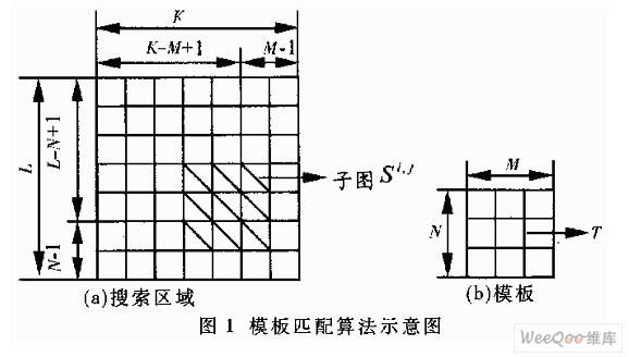
Suppose you want to find the most relevant position in the search area that is related to the template image. You can use template matching to calculate the correlation between the two. Figure 1 is a schematic diagram of a template matching algorithm. Assuming that the template (b) is superimposed on the search graph (a), the portion under the template overlay is recorded as a subgraph Si, j, where i, j is the coordinates of the top left image point of the subgraph in the S map. From Fig. 1, the range of values ​​of i, j can be obtained: 1 ≤ i ≤ K - M + 1, 1 ≤ j ≤ L - N + 1.
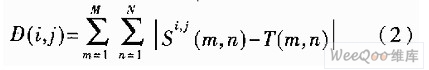
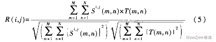
To measure the matching degree between the template T and the subgraph Si, j, the following two measures can be used:
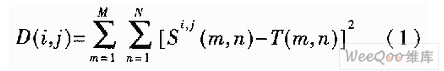
or
Expand the previous formula, which has:
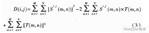
The third term on the right side of (3) represents the total energy of the template, which is a constant, independent of (i, j). The first item is the energy of the sub-image covered by the template, which changes slowly with the (i, j) position. The second term is the cross-correlation function of the sub-image and the template, which changes rapidly as (i,j) changes. The value of this item is the largest when template T and subgraph Si, j match, so the following correlation function can be used to reflect the degree of matching:

Or normalized to:
2 Establish a mathematical model
2.1 Calculation formula
The template matching algorithm calculates the similarity between the template and the matching region, and uses the most similar position as the matching point. Since the template needs to be matched successively on the matching area, the amount of operations is large. So choosing a matching formula has a great impact on the efficiency of the overall match.
The data processing capability of the industrial computer is limited. It is necessary to simplify the mathematical model according to the characteristics of the infrared thermal imaging tracking technology, and select the calculation formula with the smallest calculation amount. The target tracking algorithm is used to determine the target position. The relative size of the matching error can be used as the basis for the target discrimination. The position with the smallest error is the target position, and the absolute similarity needs to be considered.
Equations (1) to (5) can truly reflect the relative matching degree of the template, and select the formula (1) with the smallest calculation and the highest efficiency as the original mathematical model. The matching point location algorithm performs a small matching error point retrieval in the entire matching region, expressed as equation (6):

The variables K and L are the matching area sizes; M and N are the template sizes.
2.2 Template size
The effect of template size on system performance and computational load is not to be underestimated. If the template is too large, the dynamic characteristics will be poor; if it is too small, the target's feature data will be reduced, the sensitivity of the matching will be reduced, and the target detection difficulty will be increased. In practice, the effect when the template size is set to 32×16 is very good.
2.3 Matching area
In different application environments, the matching area and real-time requirements are also different. The photodetection device needs to complete the real-time processing of data in the video image acquisition cycle (20ms). Since the target moves less between the two video images and the feature changes little, the matching area can be greatly reduced.
If the matching area is too small, the dynamic characteristics of the target will be deteriorated. If the matching area is too large, the amount of calculation will be greatly increased. The specific choice needs to be weighed by the device parameters. Since the CCIR video signal is interlaced, the system processes the data in units of field for real-time considerations, resulting in a 2:1 image ratio. In order to maintain the horizontal and vertical dynamic characteristics, the image matching area is also selected in a 2:1 ratio.
When the real-time requirement is met, the relatively large matching range can be selected to improve the dynamic characteristics of the device. It can be seen from the measured data in Table 1 that the dynamic range is selected when the matching area is 100×50 points and the template is 32×16 points. It is 69×35 and the time consumption is 13ms. The target dynamic characteristics of the photodetection equipment system require that the processing area be no less than 40×20 points. It can be seen that the above selection can well meet the dynamic characteristics and real-time requirements.
Table 1 Comparison table of matching area and full optimization processing time
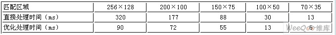
*Data test platform is: PIII933CPU, 256MB memory, Win2000 operating system
**Data is obtained with the addition of algorithm optimization and template size of 32×16.
3 mathematical model optimization method
The mathematical model combined with the selected template and the size of the search area, you can know the formula for the best matching point of the template is as follows:
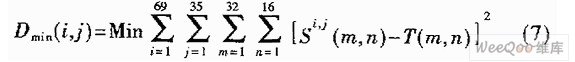
It can be seen from the formula (7) that the program needs to perform a large number of loop calculations, and the overall calculation amount is still not small, and further optimization is needed to reduce the processing time. Use the following optimization algorithm to further reduce the actual amount of computation.
3.1 rough and fine matching
Observing the actual template matching operation result, it can be found that the matching error near the matching point drops rapidly and is significantly different from other positions. In response to this feature, the algorithm of coarse and fine matching is used to quickly lock the approximate area of ​​the matching point, which can greatly reduce the overall matching times.
The specific implementation method: firstly jumps a few points to perform a rough matching, roughly frames the matching area, and then retrieves the best matching points one by one in the nearby area. The amount of computation can be reduced to less than one-third, and the target extraction effect is quite good.
3.2 Limit the maximum matching error
Since it is only necessary to find the position of the minimum matching error, it is not necessary to completely calculate the absolute matching error of each position, and the minimum matching error has been calculated as the maximum allowable error. If the calculation error is greater than the maximum allowable error, it is definitely not the best match point, and the calculation can be terminated early to enter the calculation of the next matching position; if the maximum allowable error is still less after the completion of the matching, the maximum allowable error is replaced with the current error, and Record this point as a potential matching location.
The errors of matching points and non-matching points often differ by 2 to 3 orders of magnitude. After this processing, the amount of calculation remaining after the matching point can be greatly reduced.
3.3 Out of order matching
The position where the target appears in the matching area is undefined. The unfixed sequence algorithm can retrieve the matching region faster, quickly reduce the maximum matching error, reduce the calculation of the remaining non-matching points, and reduce the overall computational complexity.
For the actual working condition of the photoelectric detecting device, the target angular velocity and angular acceleration are limited in the tracking state, and the target is often near the center of the matching region. It is best to choose a method that matches the radiation from the center to the surroundings.
4 program sample
The following program samples use the above optimization algorithm and successfully applied to the prototype of infrared thermal imaging tracking technology, achieving the expected results.
This function is used for image template matching operations and is suitable for black and white image data of 256 gray values.
Deal_With:TemplateMatch(unsigned char* lpSource, LONGlWIDTh, LONG lHeight, unsigned char* lpTemplate, LONG lTemplateWidth, LONG lTemplateHeight,)
{
Unsigned char* Source; //pointer to the image to be processed
Unsigned char*Template; //pointer to the template image
Int i,j,m,n; //loop variable
Unsigned char lMaxWidth, lMaxHeigth, / / ​​match position
Unsigned long D; //similar error
Unsigned long MaxD; //Maximum allowable similarity error
/ / rough correlation
MaxD=0x10000000; //Consult the maximum matching error
For(j=0;j
For(i=0;i
D=0;
Source=(unsigned char *)lpSource+lWidth*j+i;
Template=(unsigned char *)lpTemplate;
For(n=0;n
For(m=0;m
D+=(*Source++-*Template++)*(*Source++-*Template++);
Source+=lWidth-lTemplateWidth;
}
If(D
MaxD=D;
lMaxWidth=i;
lMaxHeight=j;
}
}
}
/ / fine correlation
lMaxWidthExact=lMaxWidth;
lMaxHeightExact=lMaxHeight;
For(j=lMaxHeight-2;j<=lMaxHeight+2;j++){
For(i=lMaxWidth-2;i<=lMaxWidth+2;i++){
D=0;
Source=(unsigned char *)lpSource+lWidth*j+i;
Template=(unsigned char *)lpTemplate;
For(n=0;n
For(m=0;m
D+=(*Source++-*Template++)*(*Source++-*Template++);
Source+=lWidth-lTemplateWidth;
}
If(D
MaxD=D;
lMaxWidthExact=i; //the best matching point position in the x direction
lMaxHeightExact=j; //The best matching point position in the y direction
}
}
}
}
Yuhai company develop and produce various plate & block sizes, electrode and metallisation configurations.This range is fabricated from 33 available Piezoelectric Material formulations for the applications of high power, sensitivity, stability needs.
Features
- Eectrode type on request
- Evaporated and chemically deposited metallisation's available
- Shear vibration plate available on request
- Thickness frequency tuning available on request
- Wide choice of PZT formulations.
Applications include
· • 1-3 Composites material available on request
· • Megasonic cleaning
· • NDT transducers
· • Pressure sensors
· • Ultrasonic sensors
• Linear ultrasonic motors
• Low frequency hydrophones
Yuhai's piezoelectric block has been utilized continuously in low frequency hydrophones in more than 30 years.
|
Plates |
Length: 1-200mm |
|
Width: 1-200mm |
|
|
Thickness: 0.2-25mm |
Piezoelectric Plate,Piezo Plate,Pzt Plate,Piezo Ceramic Plate
Zibo Yuhai Electronic Ceramic Co., Ltd. , http://www.yhpiezo.com