The dimming LED driver will have light output stability problems at low light levels. This article will explore the root cause of this problem and propose a solution. The dimming technique of bidirectional thyristors is not discussed in this paper because low light quantity instability is caused by different mechanisms. The dimming method of setting the LED current using communication technology includes DALI, 0-10V, Zigbee, and power line carrier control.
The LED driver receives a signal and uses it to set the reference current while the control loop adjusts the LED current to match the reference current. Only with high control accuracy can the brightness of adjacent fixtures be the same. The flicker and low light that occurs at low light levels is confusing for designers.
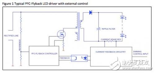
Single stage power factor correction
If a two-stage power converter is used, low light quantity instability occurs again. The first stage (boost or PFC-flyback) establishes a more stable voltage, and the second stage (usually a buck inverter) precisely regulates the current in the LED. Because of the need to use more components, the two-stage solution is not as energy efficient as a single-stage converter. For cost considerations, LED manufacturers typically use a single-stage PFC-flyback converter.
problem
The dimming should be provided in at least the interval of 20, and the incandescent lamp has no problem. At low optical power, the energy efficiency of the incandescent lamp is greatly reduced, and the power range required for the 20-light interval is relatively narrow. If 40% of the voltage or current is supplied, the light output will drop to approximately 1%. The market expects LEDs to solve this problem.
The linear response of LEDs is much better than incandescent lamps, and at lower currents, the energy efficiency is higher. The human eye can discern the difference of 5% between adjacent light sources, only reacting to the degree of difference expressed as a percentage, and the absolute amount of light does not cause human eye reaction. This requires tight control of the current, and the control accuracy is higher at low light levels. If you need to adjust to 1% of full output, you cannot use primary side control.
Unlike incandescent lamps, LEDs do not have a self-filtering mechanism. The heat capacity of an incandescent filament is a good AC filter, while an LED requires an external filter circuit. A common solution is to connect a large electrolytic capacitor directly to the LED, and the filtering effect is good.
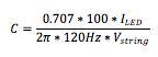
The capacity of the electrolytic capacitor is determined according to the requirements of the optical ripple. If the ripple current is less than 10% rms (approximately 28% pp), the human eye perceives the same light quality as pure DC. (Also, if the ripple current is above 10%, the ENERGY STAR logo requires a statement on the light.)
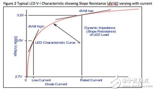
The LED has a dynamic resistance (slope resistance) that is about 1/10 of the apparent V/I resistance. Figure 2 shows the VI curve of a typical LED.
Therefore, if the ripple current is less than 10% RMS, the capacitor must control the voltage on the LED to within 1%. The required values ​​are:
Unfortunately, the capacitor is also part of the control loop. The capacitor and LED dynamic resistance set the control loop pole to approximately 30 Hz. Therefore, at this frequency, the capacitance increases by a 45-degree phase lag, reducing the loop gain by 6 dB. We will discuss this issue later. The figure below details the gain and phase shift due to the polarity of the LED control loop.
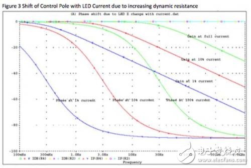
Note that the dynamic impedance of the LED increases as the current decreases. Unfortunately, this moves the control loop pole to the left. At 10% current, the corner frequency is approximately 3 Hz. At 1% current, the corner frequency is approximately 0.3 Hz. Note that for the PFC stage, a typical control loop has a crossover frequency of 3 Hz to 20 Hz.
It is unreasonable to design a control loop with a pole that is movable within this range. The only viable solution is a crossover frequency design of 0.03 to 0.1 Hz, but the control loop will become very sluggish.
UK Surface Tabletop Socket be with American type plug,could be selected to be with USB ports,Internet ports,Phone ports,overload protection and with or without switch.
US Surface Tabletop Socket can be set into furniture and office furniture like table,cabinet and so on.It will be easily to use the charging for Phone and home appliance.
Specifically, We have our own design and production team for USB Circuit Board design and produce.
US Surface Tabletop Socket
Power Outlet Strip,USSurface Tabletop Socket,USA Surface Mounted Power Strip,USSurface Mounted Power Strip
Dongguan baiyou electronic co.,ltd , https://www.dgbaiyou.com