Guide: With the birth of white LEDs and their rapid development, LEDs began to enter the general lighting stage. LED is a solid-state cold light source, the fourth generation of electric light source after the incandescent, fluorescent and high-intensity discharge lamps (HID). It is now widely used in the fields of building lighting, street lighting, landscape lighting, signage, signal lights, and lighting in residential buildings.
There are currently three main types of LED-powered power supplies: low-voltage batteries, solar cells, and AC mains. Regardless of which raw power source is used, it must be converted to meet the operating conditions of the LED. Such a power conversion circuit generally refers to an LED driving circuit. In LED solar power systems, batteries or supercapacitors are also needed to store solar energy. When lighting is required at night, the battery or supercapacitor is discharged through the control circuit to supply power to the LED drive circuit.
The combination of solar and wind energy and LED is a highlight of LED applications. It will bring light to the poor and remote areas of the Third World, and let the brilliance of green lighting illuminate every corner of the world.
1. Low-voltage DC-powered LFD drive circuit
1. When the input voltage is higher than the LED voltage
When the input voltage is higher than the voltage drop of the LED or LED string, a linear regulator or a switching buck regulator is usually used.
(1) Linear regulator
The linear regulator is a DC-DC buck converter. Most of the linear regulators used in the LED driver circuit are low-dropout regulators (LDOs), which have the advantage of not requiring inductive components, requiring a small number of components, no EMI, and low voltage drop. However, compared with switching regulators, LDOs have higher power losses and lower efficiency. LDOs often need to add a heat sink when driving high-power LED strings of 350mA or more.
(2) Switch type buck regulator
A switching buck regulator based on a monolithic dedicated IC requires an inductive component. Many buck regulators have switching frequencies above 1MHz, resulting in very small external components, occupying very small space and achieving efficiencies of over 90%. However, such converters generate switching noise and have EMI problems. Figure 1 shows a 3W LED step-down driver circuit based on the Zetex ZXSC300. The RCS is a current sensing resistor, and D1 is a 1A Schottky diode. At an input voltage of 6V, the current through the LED is 1.11A. The ZXSC300 is available in a 5-lead SOT23 package.
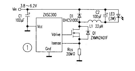
There are many buck converter monolithic ICs that integrate the switching MOSFET (Q1) and the buck diode (D1) on the same chip, further reducing the number of external components.
2. When the input voltage is lower than the LED voltage
When the input voltage is lower than the total forward voltage drop of the LED or LED string, the LED requires a boost drive circuit. There are two main types of boost converters.
(1) Inductive boost converter
In mobile phone backlighting, an inductive step-up LED driver circuit is often used. A switched inductor boost converter is used to drive a string of LEDs consisting of one or more LEDs with equal current through each LED. If one LED is open in the LED string, the other LEDs will go out. Figure 2 shows the inductor-boost LED driver circuit. The LED string consists of eight NSPW500BS white LEDs from Nichia Chemical Co., and the current through each LED is about 25mA at an input voltage of 4V.
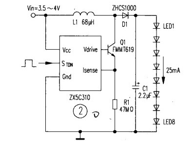
At present, most of the boost regulator ICs integrate the switching transistors in the chip, and some also integrate Schottky diodes.
(2) Switched capacitor (charge pump) boost converter
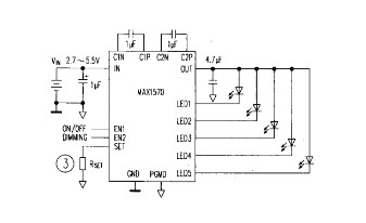
The switched capacitor boost converter is also a charge pump. The charge pump dedicated IC has a built-in switch, and is connected to one or two 1μF charge and discharge capacitors. The charge pump operating modes are 1×, 1.5× and 2×, and in recent years there have been 1.33×(4/3 times) and 4× modes. When the output voltage is close to the input voltage, the charge pump does not need to be boosted, ie, operates in 1X mode. When boost is required, switch to 1.5x or other operating mode. The charge pump circuit can drive the LED array or drive only one LED. Figure 3 shows the MAX1570-based charge pump driving five white LEDs. The MAX1570 is available in a 4mm x 4mm 16-pin QFN package with a maximum thickness of 0.8mm. The MAX1570 has an input voltage range of 2.7V to 5.5V, operates at a fixed frequency of 1MHz and operates efficiently in 1x and 1.5x modes, providing 30mA for LEDs. Constant current, LED current matching accuracy of 0.3%, and LED current can be set by a single resistor RsEr. LED brightness can be controlled via digital input or PWM, consuming only 0.1μA in the off state.
3. When the input voltage may be higher or lower than the LED voltage
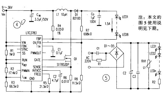
A buck/boost converter must be used when the input voltage can be higher or lower than the total voltage drop of the LED or LED string. A circuit based on the LT°C3783 buck/boost converter drives eight 1.5A series LEDs as shown in Figure 4. The input voltage range of the LED string driving circuit is 9~36V, and the total voltage drop of the LED string is 18~37V. Under the condition of VIN=14.4V, Vo=36V and I0=1.5A, the output power is 54W, and the efficiency is up to 93%. The switching frequency of the circuit is determined by the IC pin FREQ
Resistor R5 is set (frequency range is 20kHz~1MHz). The voltage divider composed of R7 and R8 sets the output overvoltage protection level. R4 is connected between IC pin FBP and the high side line to sense the LED current. The LTC3783 supports multiple topologies. It can also be used to construct circuits such as boost converters and buck converters.
Flyback converters, single-ended primary inductor converters (SEPIC), and CUK regulators can all increase or decrease the input voltage.
The output and input voltage can be the same or opposite in polarity. Each topology has unique advantages, but is less efficient than a buck-boost regulator.
Second, AC mains power supply LED drive circuit
1. Capacitor step-down LED driver circuit
Figure 5 shows the capacitor step-down LED driver circuit (Note: Figure 5 circuit is shown in the previous edition). In the figure, C1 is the step-down capacitor, R1 is the bleeder resistor, DI~D5 is the bridge rectifier, C2 and C3 are the filter capacitors, RVl is used as the transient overvoltage protection, and R2 is the current limiting resistor. At 220V50Hz input supply, the current through capacitor C1 is I=69C1 (C1 is μF, I is mA). If C1 is selected to be 0.471μF, the current is approximately 32mA. In this case, the value of R1 can be selected as 1MΩ.
Capacitor step-down LED driver circuits are only suitable for low power applications, do not provide large drive currents, and are very inefficient. The advantages are low cost and simple circuit.
2. Transformer step-down LED driver circuit
An LED driver circuit using a power transformer step-down is shown in Figure 6. The secondary output of the transformer is 12Vac, the forward voltage drop of the white LED is VF=3.5V, the forward current is IF=350mA. The bridge rectifier voltage is 12Vx2, and the current limiting resistor R1 is R1=(12V× 2-3xVF)/ IF = (12V × 2-3 × 3.5V) / 350mA = 18.3Ω
Select R1=20Ω. The power consumption of R1 at 350mA is 0.352×20=2.45W, and a 3W resistor can be selected. At Ω of R1=20, the current through the LED is:
ILED=(12V× 2-3×3.5V)/20Ω=323mA
If the bridge rectifier input voltage fluctuates by ±10%, the LED current at 10.8Vac is 238mA, and the LED current at 13.2Vac is 429mA, resulting in a LED current change rate exceeding ±25%. This shows that although Figure 6 The circuit shown is relatively simple, but the current adjustment capability is poor, and the power transformer is large and cumbersome, and it is not easy to achieve miniaturization and weight reduction of the circuit.
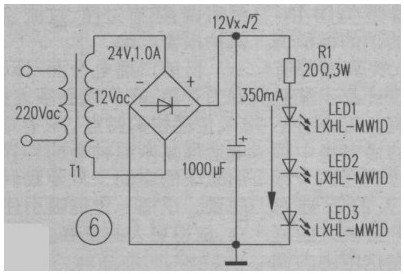
Figure 7 shows the white LED driver circuit with linear regulator MC7809. The AC input voltage (12Vac) is the power transformer (or electronic transformer output. The DC output voltage of the MC7809 is 9V, R1 value is: R1=(Vout- 2×VF)/IF(9V-2x3.5V)/350mA=5.7Ω R1 The power consumed is:
p=12×R=(0.35A) 2×5.7Ω=0.698W
The power consumption of the MC7809 is: P = (12V × root number (2) 2-9V) × IF = (17-9V) × 0.35A = 2.8W After using a linear regulator, the current regulation rate is ± 5%, but The power dissipation is large and the efficiency is low.
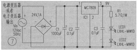
If the linear current source NUD4001 produced by ON Semiconductor is used instead of the linear regulator, the current regulation rate can be less than 1%, and the NUD4001's own power consumption is only 0.875W at 350mA.
3. Switching regulator
The off-line LED driver circuit based on the switching power supply topology can achieve high efficiency of about 80%, and can provide constant current and constant voltage output, but the circuit is more complicated, the cost is higher, and in some cases there is EMI problem.
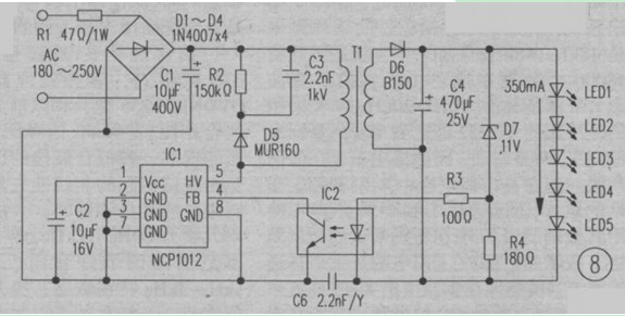
Figure 8 shows the circuit for driving five white LEDs based on the controller NCPl012's flyback (flyback) converter. The circuit has an output DC voltage of 17.5V, an output power of 6.125W, and an efficiency close to 80%. The NCP1012's switching frequency is 65kHz, providing dynamic self-powered (DSS), over-voltage and short-circuit protection, and over-temperature protection without transformers. Winding. External components are further reduced due to the integration of power MOSFETs on the chip.
In order to meet the needs of landscape lighting, industrial lighting and architectural lighting, there have been many offline controller chips for driving LEDs. As portable devices such as mobile phones have become saturated, LED applications will shift to landscape lighting, automotive and large-screen displays, and general lighting. The off-line switching LED driver circuit will become the dominant topology in the future. LED solar power supply system will have a big development.
Place of Origin:Dongguan, China (Mainland)
Gauge: AWG 28 to AWG 16
Length: Customized
A perfect replacement of the broken or old windshield washer nozzle
Connector: Molex, JST, TYCO, AMP, JAM, KET,Amphenol, Wago,Weidmuller, Phoenix,
Wires & Cables: UL, VDE standards
Inspection: 100% inspection before delivery
Certification UL, IATF16949, CE,
Car Wiper Blades,Obd Jumper Harness,Electrical Cable Gland,Auto Wiper Blade
Dongguan YAC Electric Co,. LTD. , https://www.yacenter-cn.com