0 Preface
OpTIcal Orthogonal Frequency Di-vision MulTIplexing (O-OFDM) technology is a new type of optical transmission technology that has emerged in recent years. It is based on Orthogonal Fre-quency Division MulTIplexing (Orthogonal Fre-quency Division MulTIplexing, OFDM) technology is a technology used for Fibre Channel. The transmission of OFDM signals in the Fibre Channel can improve the utilization of the spectrum, and is well resistant to chromatic dispersion and various noise interferences, and has a higher transmission rate and bandwidth. However, since the OFDM signal is superimposed by a plurality of modulated subcarrier signals, it is possible to generate a large peak-to-average ratio (PAPR), which directly brings about a nonlinear effect of the transmission medium-fiber, mainly including Self-phase modulation (SPM), mutual bit modulation (XPM), and four-wave mixing (FWM). By studying the influence of fiber nonlinearity on the transmission of OFDM signals in optical fiber, the variation law of the signal can be obtained to find a suitable signal compensation method.
1 The basic principle of optical OFDM
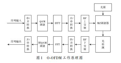
The basic O-OFDM system structure is shown in Figure 1. The original binary sequence is mapped to N parallel subcarrier channels by serial/parallel conversion. At this time, the data period of each modulated subcarrier is expanded to N times of the original sequence, and the numerical ratio of delay spread and symbol period is also reduced. N times.
Then, after performing QAM modulation on the sequence on each subcarrier channel separately, performing inverse Fourier transform (IFFT), the expression in the frequency domain of the data is transformed into the time domain, and the number of transmitted bits is respectively mapped to the amplitude of the subcarriers. Phase. Then, the signal is subjected to parallel/serial conversion, and then the signal is subjected to I/Q conversion and up-conversion, and after passing through the Mach-Zehnder modulator, the electrical signal is converted into an optical signal and sent to the optical fiber for transmission. After light detection, down-conversion and I/Q demodulation, the signal is restored to an electrical signal, and then the signal is mapped to N parallel subcarrier channels through serial/parallel conversion, and then subjected to Fourier transform FFT to time domain. The signal is changed to the frequency domain, and after QAM demodulation and parallel-to-serial conversion, the signal is restored to a serial output sequence.
2 Optical OFDM signal transmission in optical fiber
The model of OFDM signal transmission in fiber can be described by the nonlinear Schrödinger equation (NLSE):
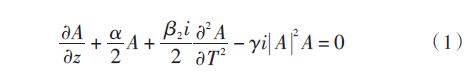
Where: A(z,T) is the slowly varying amplitude of the pulse envelope; z is the distance the pulse travels along the fiber; T = t - β1 z, β1 = 1 Vg , Vg is the group velocity; α is the fiber loss coefficient; Β1, β2 are first-order and second-order dispersion coefficients, respectively; γ is a nonlinear coefficient. Normalized amplitude: U = A(z,T) P0 , P0 is the peak power of the incident pulse. At this time, formula (1) can be written as:
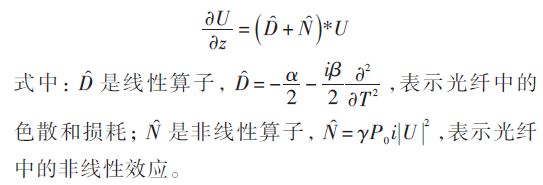
Since the nonlinear Schrödinger equation generally cannot directly find the analytical solution, it is necessary to find a numerical solution. The step-by-step Fourier transform method is one of them. The idea of ​​the distributed Fourier transform method is to select an optical signal transmission distance h. When h is small, the effects of dispersion and nonlinear effects on the pulses can be calculated separately, and approximate results are obtained. When the optical pulse transmits h 2 in the optical fiber, the dispersion effect is calculated; then the nonlinear action is calculated in z + h 2 ; the dispersion effect is calculated after the optical pulse continues to transmit h 2 , and an approximate solution with a transmission distance h is obtained. Finally, the result of the integrated dispersion effect and the result of the nonlinear influence are obtained as an approximate solution when the optical pulse signal transmits a distance h in the optical fiber.
3 Simulation results and analysis
3.1 Simulation process
(1) Generating an OFDM electrical signal: setting a QAM modulation index and a number of subcarriers, and modulating a random sequence into one OFDM signal.
(2) Modulation light source: The OFDM signal is modulated by the OFDM signal obtained in the previous step to obtain an optical OFDM signal.
(3) Step-by-step Fourier method solution: set the fiber channel parameters and algorithm step size, use the step-by-step Fourier method to solve the nonlinear Schrödinger equation, simulate the process of optical OFDM signal passing through the fiber, and obtain the signal after transmission through the fiber. .
(4) Photoelectric detection: photoelectric conversion is performed to convert a signal transmitted through an optical fiber into an electrical signal.
(5) Signal compensation processing: According to the parameters of the OFDM signal and the parameters of the optical fiber, the corresponding signal amplitude and phase are compensated to eliminate the influence of dispersion and attenuation of the optical fiber.
(6) OFDM demodulation: Demodulation of the OFDM signal according to the QAM modulation index and the number of subcarriers of the OFDM signal, and recovering the original signal sequence.
(7) Error analysis: Compare the input sequence of the sender and the output sequence of the receiver to analyze the system error characteristics.
For the sake of simplicity, other devices are considered to be ideal devices, considering only the effects of the fiber on the signal.
3.2 Simulation results
3.2.1 Calculation of bit error rate
For an input sequence, the reference sequence obtains the transmitted sequence to derive the error characteristics. The peak-to-average ratio distribution of the signal can be counted by a large number of randomly generated input sequences, and the error rate at the corresponding peak-to-average ratio is calculated, and the system error rate distribution and the average system error rate can be obtained.
The LED exit sign light is specially made from aluminum and acrylic materials, and is also fast dissipating heat, insulating and corrosion resistant. LED emergency lights are illuminated with super bright LEDs to ensure visibility in dark corridors and hallways. In case of an emergency power outage, the exit lane will be illuminated. Exit signs are designed for various types of indoor commercial uses such as hotels, shopping centers, theaters, restaurants and other public places. Any emergency exit signs must have continued reliability. Easy to install and can be hung on the wall or from the ceiling.

Exit Sign For Aluminum And Acrylic
Emergency Light Sign,Wall Mounted Exit Sign,Led Emergency Exit Sign,Battery Operated Exit Signs
Jiangmen City Pengjiang District Qihui Lighting Electrical Appliances Co., Ltd , https://www.qihuilights.com