In order to meet the needs of many systems, a wave of charger ICs is emerging among system designers and charger IC suppliers. The charger IC mentioned in this article refers to a charger IC in a device such as a smart phone/tablet for converting the power of the AC/DC adapter (or USB) into a form suitable for battery charging. Recently, the focus of charger ICs has been the increasing popularity of high efficiency switching chargers and the rapid replacement of existing charger solutions based on linear or pulsed methods. As for the reasons, there have been too many articles discussed.
This article mainly introduces the power path characteristics of the charger IC. Power paths often come under different names, and there are multiple implementations. System designers can therefore be plagued by how trade-offs can be made between different scenarios. A broad definition of a power path is one or more of the following advantages:
1. Power sharing between system and battery
2. Power the batteryless system
3. Power the system with a completely exhausted battery
The block diagram of Figure 1 is a typical implementation of a power path using an "ideal" diode. The current is indicated by the arrow and it can be seen that the "ideal" diode (whether internal or external) contributes to proper control of the current.

Figure 1. Power path implementation with "ideal diodes"
Although this implementation can meet the power path standard, in reality the diode cannot be truly "ideal". For example, the internal diode of such an IC is actually a PMOS with a resistance of typically 180m?, which means that there is always a 180m? energy-consuming series component between the battery and the system load, which consumes a large current in the battery ( For example, GSM pulses) generate considerable additional power consumption. Using a parallel PMOS switch reduces this impedance value, but it also increases the size and cost of the solution.
The implementation of Figure 2 differs from the solution shown in Figure 1. The circuit in Figure 2 does not seem to have power path functionality on the surface, but in fact it can meet almost all of the requirements. In addition, it has the great advantage that there is no energy-consuming series component between the system load and the battery.

Figure 2. Schematic of the FAN5400 module
System and battery power sharing
Power sharing between the system and the battery means that power can be controlled or prioritized to the system in case the input power is insufficient to simultaneously power the system and charge the battery.
A typical configuration of the FAN5400 is shown in Figure 3, where the system is connected in parallel with the battery. The power control of this configuration is similar to the power path and can sometimes be confusing, so the actual situation based on the actual battery capacity and the number of input power sources is given below.
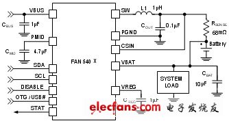
Figure 3. Typical application circuit with the system in parallel with the battery
Example 1:1500mAh battery (1C maximum charge current capability of the battery is 1500mA), input power supply is 5V/500mA USB 2.0
Case A) Partially charged battery with 3.6V and system load 400mA turned on.
The charger is already in CC mode before the system load is turned on. Since the input power is 5V 500mA and the battery voltage is 3.6V, approximately 632mA can be used for battery charging. This value is calculated in consideration of the converter conversion efficiency and the output current multiplication factor obtained when the voltage is lowered.
![]() (1)
(1)
From these values ​​in this example, 5V/3.6V•500mA•91%=632mA can be obtained. A 91% efficiency data point can be found in Figure 4.

Figure 4. Conversion efficiency of FAN5400 to battery voltage and VBUS voltage
When the system load is turned on, the 400mA current steering system, leaving only 232mA for battery charging. This is equivalent to power steering; for chargers, the system has a higher priority than the battery. When the system load is turned off, all of the 632 mA current flows to the battery again. As shown in Figure 3, the FAN5400 has the advantage that there are no energy-consuming series components between the system and the load.
Case B) Partially charged battery with 3.6V and system load 2000mA turned on.
Before the system load is turned on, similar to Case A, the charger is already in CC mode and all input power is used to charge the 632mA battery. When the system load is turned on, the 632 mA current is diverted to the system and the remaining 1368 mA load current is supplied by the battery.
This is equivalent to power control; for the charger, the system has priority over the battery. When the system load is turned off, all of the 632 mA current flows to the battery again. Similarly, the circuit of Figure 3 has the advantage that there is no energy consuming component between the system and the load.
Case C) Fully charged battery with 4.2V and system load 400mA turned on.
The charger is turned off before the system load is turned on. When the load is turned on, all system power comes first from the battery. Once VBAT "VOREG - VRCH, the charger will start. VRCH is the recharge threshold of 120mV. Since the input supply is 5V 500mA, the maximum available current that the charger can supply is 5V/4V•500mA•92%=575mA (this assumes a battery voltage of 4V). When the charger is started, the charger's charging current should be 575mA. However, since the system load still exists, only 575mA-400mA=175mA actually flows into the battery.
This is equivalent to power control; for the charger, the system has priority over the battery. When the system load is turned off, all of the 575 mA current flows to the battery until the battery enters CV mode, at which point the charging current begins to decrease. Similarly, the circuit of Figure 3 has the advantage that there is no energy consuming component between the system and the load.
Case D) Fully charged battery with 4.2V and system load 2000mA turned on.
The charger is turned off before the system load is turned on. When the load is turned on, the power comes first from the battery, and the battery charger starts up almost immediately and enters CC mode. This is because lithium-ion batteries generally have a 150m? output impedance, which makes VBAT VOREG-VRCH almost immediately. Similar to Case C, the charger attempts to charge the battery at 575 mA (actually slightly higher than 575 mA because the battery voltage is lower than Case C and the multiplication factor is slightly higher in this case. However, since this is a demonstration experiment So can be ignored without considering). The charger tried to charge, but since the system load was 2000mA, 575mA of current flowed to the load, and the remaining 1425mA of system load current was supplied by the battery.
This is equivalent to power control; for the charger, the system has priority over the battery. When the system load is turned off, all of the 575 mA current flows to the battery until the battery enters CV mode, at which point the charging current begins to decrease. Similarly, the circuit shown in Figure 3 has the advantage of having no power components between the system and the load.
The cooling system of water-cooled computer can not leave the water pump, water pump is the key to push the liquid flow. Water pump is a heart of one water cooling system, without water pump, the whole will not form a circulation, water pump of the water cooling likes the engine if the car, they both have the output power.displacement.rotate speed and so on,Water pumps correspond to lift, flow speed and power.
12V Dc Mini Water Pump For Pc,Dc Mini Water Pump,12V Dc Mini Water Pump,Pressure Water Pump
Dongyuan Syscooling Technology Co., Ltd. , https://www.syscooling.com