Abstract: The main content of this paper is to design and implement an LED car light control system. The implementation principle of the control system is expounded in the paper, and the design and implementation process of software and hardware are introduced in detail. The system uses the XC164CM single-chip microcomputer as the control core, which mainly realizes the control functions such as adaptive adjustment of the brightness of the lamp, state monitoring, and human-computer interaction. The experimental results show that the system has stable performance and can be widely used.
Key words: XC164CM single chip; LED; adaptive; vehicle light control system; CAN bus
In modern driving safety systems, the vehicle light control system plays an important role. According to the data, most of the traffic accidents occur at night or in bad weather. Most of these traffic accidents are caused by the failure of the vehicle control system to meet the safety requirements in time. For example, the traditional lamps have a single brightness and a wider line of sight. Short, can not automatically adjust the brightness and mode with changes in the external environment, sometimes causing energy waste, and sometimes can not meet lighting needs. Therefore, designing a more practical and intelligent vehicle light control system has become a top priority.
The vehicle lamp control system developed in this paper adopts LED lamps with high luminous brightness, fast response speed, harsh environment and reliable working performance, which improves the brightness and viewing angle range, reduces the safety distance, and effectively improves the driving safety performance. The system uses sensor technology, microprocessor technology, electronic circuit technology and CAN bus technology to achieve accurate sensing and judgment of ambient brightness and driving conditions, and automatically selects the appropriate lighting mode according to driving needs, thus realizing the lights of the vehicle. Adaptive Control. The controller can effectively assist the driver to drive, reduce the driver's operation burden, and avoid the use of lights caused by human factors to the maximum extent, thus achieving the purpose of reducing traffic accidents.
1 headlight control system
1.1 System working principle The system senses the brightness of the environment and the temperature of the control panel through an external sensor, converts it into a voltage-dividing signal of the photosensitive and the thermistor and the LED driving voltage-dividing signal, and is performed by the single-chip AD module. collection.
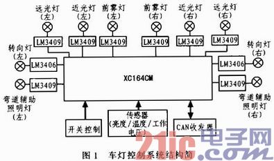
The MCU analyzes and classifies the digital information after AD conversion according to the pre-divided level, and judges the current driving environment of the car (daytime, rain and fog weather, outdoor evening or late night, car, tunnel, etc.), and then with built-in The characteristic parameters are compared and the switch brightness is automatically selected after the switch scan. According to the selected parameters, the XC164CM outputs the corresponding PWM signal to adjust the brightness of the lamp.
The current state of the headlights can be sent to the host computer through the CAN bus interface, and the host computer can also send adjustment information to change the state of the lights, thereby realizing the human-computer interaction function. The system structure is shown in Figure 1.
This article refers to the address: http://
1.2 System function design The LED lamp control system designed in the text has completed the following functions.
1.2.1 Adaptive adjustment of brightness The ambient brightness of the outside world is divided into three levels: bright (clear sunny, etc.), dim (outdoor rainy, outdoor evening, tunnel, parking lot, etc.), dark (outdoor late night or other) Similar occasions). The system can automatically adjust the brightness of the lights according to the brightness level of the current environment to meet the lighting needs in different situations. The brightness of the lights is divided into 4 levels, 6 levels, and 8 levels of brightness, of which 4 is the darkest, 8 is the brightest, and 6 is the middle. The adjustment strategy of the brightness of the lamp is as follows:
1) When the ambient brightness is increased, the brightness of the signal light is increased; when the ambient brightness is weakened, the brightness of the light is enhanced.
2) Since the brightness of the lamp is reduced instantaneously, there is a certain risk. Therefore, when reducing the brightness of the lamp, it is necessary to make two judgments: when the ambient brightness is increased, the brightness of the lamp does not immediately decrease, but continues to wait for one cycle. If the ambient brightness remains at a low value and does not change, dim the light; when the ambient brightness is weak, do the same for the signal.
1.2.2 Status monitoring and over-temperature protection Real-time monitoring of the voltage output from the driver to the LED lamp and displaying the result through the host computer. The LED lamp is defined as three states: fault state, off state, and working state. These three working states are distinguished by the current working voltage and switching state of the LED lamp. Over-temperature protection is achieved by monitoring the operating temperature of the drive in real time. When the ambient temperature of the drive exceeds 80 degrees, an over-temperature warning signal is generated to prompt the selection of the temperature control mode (drive output derating is allowed).
1.2.3 The human-computer interaction control system is connected with the host computer CAN receiver through the CAN bus interface provided by the XC164CM MCU to realize the interaction with the host computer information. The host computer can not only query and obtain the digital status (fault state, off state or brightness level) of the working state of the lamp, but also send control commands to adjust the brightness of the lamp and enter the intelligent lighting mode, thereby realizing human-computer interaction.
2 hardware design hardware is mainly composed of single-chip control module, sensor module, CAN bus module and LED driver module.
2.1 XC164CM MCU Introduction XC164CM MCU is an enhanced 16-bit MCU produced by Infineon using low-power CMOS technology. Its main features are: 1) using C166SV2 core; 2) internally integrating large-capacity memory; 3) Self-checking 14-channel A/D converter; 4) Two comparisons, the capture unit can easily generate PWM waves; 5) The Twin CAN module can exchange data through the gateway.
2.2 Sensor device Ambient brightness is collected by 3 sets of brightness sensors located at different positions (front, side, top). The brightness sensor is a photoresistor GM5528 (light resistance 10-20 kΩ, dark resistance 1 MΩ, response time 20-30 ms) installed at the photosensitive position, and the voltage value output by the GM5528 through the voltage dividing circuit changes with the change of the ambient brightness; The temperature monitoring circuit uses the thermistor MF58 to form a voltage dividing circuit, which converts the change of the temperature value into a change of the voltage value; the state monitoring circuit separately samples the output voltage of the 10 LED drivers through the resistor voltage dividing network, and judges the LED light by using the resistor voltage dividing network. Working status.
2.3 CAN control module XC164CM MCU integrates the TwinCAN module to realize the CAN bus communication function. Its main features are: 1) It includes two full CAN function nodes. Each CAN node is connected to the bus transceiver through a pair of receiving and transmitting pins, which can work independently or exchange data frames and remote frames through the gateway function. 2) CAN frame transmission and reception follow the CAN V2.0B (active) specification, and each CAN node can receive and transmit standard frames with 11 identifiers and extended frames with 29-bit identifiers. 3) With flexible and powerful message transmission control and error handling capabilities, CAN bus communication processing is more precise and convenient. 4) The bit timing of the two CAN nodes is derived from the peripheral clock and can be programmed to achieve a data rate of 1 Mbps. 5) Has 8 separate programmable interrupt nodes and FIFOs for transmit and receive.
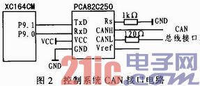
The system connects the CAN communication module through the CAN bus interface of the XC164CM single-chip microcomputer and the MCU development board using the SJA1000 controller and the 82C250 transceiver to realize the human-computer interaction function.
The circuit diagram is shown in Figure 2.
2.4 The LED driver driver module refers to the Xigongda LED driver power supply standard. The signal lamp uses the LM3406 driver with a power range of 3 to 15 W. The illumination lamp uses the LM3409 driver with a power range of 20 to 45 W.
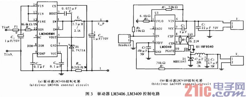
The LM3406 driver is a buck regulator with a wide input voltage range, low reference voltage and two-wire dimming. It provides up to 1.5 A of forward current and is the ideal constant current supply for LEDs. The chip has an integrated circuit that ensures an average current output. When the converter is in continuous conduction mode (CCM) operation, the controlled on-time structure ensures that the switching frequency is constant regardless of changes in the input and output voltages. Therefore, the output current of the LM3406 is extremely accurate and the transient response is also Extremely fast, the switching frequency can be kept constant under different conditions.
The LM3409 is a buck-stabilized P-channel MOSFET controller that provides a wide input voltage range with high-side current sensing in an enhanced thermal-dissipation eMSOP-10 package. Therefore, the LM3409 is an ideal constant current source for driving LEDs with a forward current of up to 5 A. In addition, the LM3409 uses constant off-time (COT) control to adjust current, ensure constant output current, and eliminates the need for loop compensation through external components. Analog and PWM dimming functions can be easily implemented to maximize brightness and linearity. And the advantages of high contrast, and provide programmable undervoltage lockout, low power shutdown and thermal shutdown.
The signal and illumination driver structure uses NI's LM3406 and LM3409 as the BUCK circuit of the main control chip. The temperature range of the chip is -40+125°C. The circuit principle is shown in Figure 3.
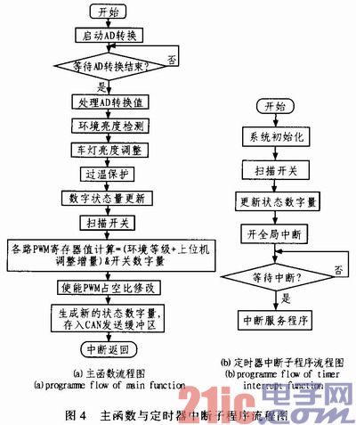
3 The software design program mainly adopts the interrupt control mode. The system flow mainly includes the main function, the timer interrupt subroutine, and the CAN receiving interrupt subroutine. The specific system flow chart is shown in Figure 4.
3.1 Main function part 1) Initialization part: Set the input and output status of each port, initialize each module and start the timer.
2) Switch scanning: 6-way switch is used to control the opening and closing of 10 lights. When the switch is closed, it outputs a low level, which corresponds to the on state of the LED light; when the switch is turned off, it outputs a high level, corresponding to the off state of the LED light.
3) Status digital quantity generation: The status digital quantity is 16-bit data, the status bit (higher eight bits) indicates the drive status, and the flag bit (lower eight bits) indicates the drive number. The initial brightness of the lights is set to level 6.
4) Enable the global interrupt, wait for the timer interrupt signal and the CAN bus communication interrupt signal, and enter the corresponding interrupt service routine after receiving the interrupt signal.
3.2 Timer Interrupt Subroutine The timer generates a timer interrupt signal every 20 ms and enters the timer interrupt service routine. The operations implemented in the timer interrupt service routine are:
1) Turn on the AD conversion, wait for the AD conversion to complete, and normalize the AD sampling result.
2) Ambient brightness detection: In order to avoid misjudgment of brightness information, the detection result is considered only when the photosensitive resistors in the three directions of the front, side and top of the vehicle body simultaneously detect the change of the brightness value (and simultaneously exceed the judgment threshold). Effective, determine the brightness level of the environment, and send the result to the lamp brightness adjustment program. If the three photoresistors do not detect the change in the brightness value at the same time, it is considered that only the brightness difference caused by the external interference, and the brightness of the driving environment does not change.
3) While detecting the ambient brightness, the switching quantity of the 10 LED lights is also detected and updated.
4) Lamp brightness adjustment: compare the detected ambient brightness with the previously detected ambient brightness, and adjust the brightness according to the comparison result. The specific adjustment strategy is in Section 2.2.
5) Over-temperature protection: Compare and judge the temperature results of the sampling. If the temperature exceeds 80 degrees, first generate an over-temperature warning message, prompting the control system to enter the derating application, set the derating flag to 1, and reduce the driver power by half. Zero the derating flag.
6) State digital quantity update: First, normalize the AD sampling result, compare the conversion result of the driver voltage signal with the measured working voltage, and determine that the out of range is fault state, generate status bit 101, otherwise use The value of the brightness level register is used as the status bit. Second, the resulting status bit is matched with the switch register value (switch register value table: on to 1, off to 0) to get the final status bit. Finally, the status bits form a status digital with the drive flag and place it in the CAN transmit buffer.
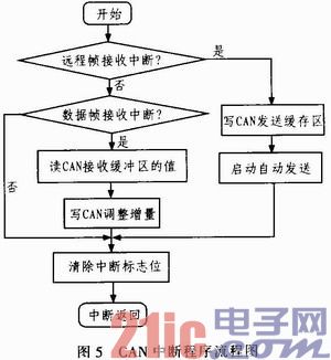
3.3 CAN Receive Interrupt Subroutine 1) After the CAN bus interface receives the information correctly, set the interrupt flag bit and enter the receive interrupt service routine.
2) Determine whether the interrupt is a remote frame interrupt, if yes, write the status quantity information to the CAN module transmission buffer area, and start automatic transmission; otherwise, further determine whether the data frame reception is interrupted. If it is a data frame reception interrupt, the value of the CAN receive buffer is read and written to the CAN adjustment amount. Finally, the corresponding flag is cleared and returned to the main function. The flow chart is shown in Figure 5.
4 Conclusion In this paper, a high-end automotive lighting control module based on XC164CM single-chip microcomputer is designed. This module not only completes the brightness control of each headlight, but also realizes the state detection of each headlight. The working process of the car lighting control module is a continuous cycle of detection process. The brightness information is continuously updated by comparing the detection results twice before and after, and then the brightness of the lamp is adjusted according to the updated brightness information, thereby realizing the adaptive adjustment of the brightness of the light. . In the course of the experiment, LED5050 white light was selected as the lamp experiment light, and equipped with the lamp cover to make the vehicle lamp simulation demonstration board. Between the lamp load and the MCU interface, the experimental circuit is independently developed, and a 6-way switch is set on the experimental circuit to realize the on/off control of the 10-way lamp. The experimental results show that the system has stable performance, realizes all the functions of the design, and can return the result correctly.
Shareconn development Co.,Ltd manufacture series electric wire harness. We equipped with high-end automatic production equipment, like automatic crimping machines, automatic wire cutting and crimping machines, automatic crimping and tinned plate machines, etc. Meanwhile, we have our own laboratory to support the testing requirements from our suppliers and 100% checking before shipment. To assure the product and the comprehensive competence, we introduce high-level technical talents and management personnel as well as well-trained staff, and improve ourselves in many ways, like the quality, price, delivery, service, etc. Now, Shareconn has been the best supplier and partner for many customers.
Electronic Wire Harness,Electrical Wire Harness,Auto Electronic Wire Harness,Electronic Wire Harness
Shareconn Development CO.,LTD , http://www.share-conn.com