"Cree XLamp® power devices latest update application guidelines and Precautions"
- Chip Application Notes
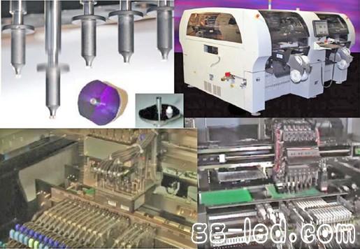
Introduced into a high-power LED many variables that may affect the performance of the patch in the patch system manufacturing process. LED require specific process parameters on chip equipment, to optimize system performance. This is primarily due to the dome material and weight distribution of the LED components. Since high-power LEDs with soft-molded silicone have been in use for about 5 years, and the placement process can still be significantly optimized to ensure that these components can be placed like the SMDs already in use.
Cree understands that to make solid-state lighting products successful, it is not only necessary to use the best and brightest LEDs on the market, but also the key to achieving high-yield knowledge and technical support for processing these components in a high-speed, precise process. Out, low defect rate and zero damage to the LED. Cree has been working with a number of SMT equipment manufacturers to help customers identify the best options available, maximizing the performance of their systems through modifications and adjustments, minimizing mistakes and increasing throughput.
How to assist in troubleshooting the automatic placement system;
How to confirm the hidden factors of the patch process, including picking, aligning and placing;
How to identify solutions that help reduce mistakes;
How to take advantage of offering solutions from automated system manufacturers.
I. Hidden factors
Figure 1 below illustrates the important areas of concern for reducing the failure rate. The failure rate is incremented next to each layer of the pyramid. In many cases, patch failures can be resolved with quick fine-tuning, but fine-tuning can actually have little effect if there is something more important to deal with. First, you must deal with more important issues. The best way to solve the important factors of the patch problem is to start with the bottom of the pyramid below and make sure to follow the advice of the LED manufacturer and the manufacturer of the placement equipment. Cree has partnered with several SMT equipment suppliers to launch a collaborative program and work with them to provide products and recommendations.
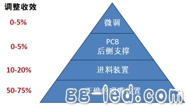
Figure 1 Troubleshooting pyramid and expected results
1. Correct nozzle setting
The first step in troubleshooting is to make sure you are using the correct nozzle settings. This is the easiest step and can receive the fastest improvements. The placement system handles a wide range of components and can process 1-30 parts at a given time. SMD pick-up nozzles and process parameters have been developed for many years, but the softer LED silicone dome requires a specific nozzle material. In the past, metal and steel patch nozzles were standard, but since silicone can be used as a gasket and form a metal tube seal, the release of the LED component after placement can be problematic. Considering the interaction between this silicone dome and the steel nozzle, some placement equipment manufacturers and third-party suppliers have developed nozzle materials to improve the placement or release of soft silicone LEDs. These materials are listed in nozzle "Cree and welding process" document, recently discovered polyurethane nozzle can get some of the best results.
2. Feeding device
After properly configuring the nozzle, the next step is to investigate the feed unit. When the part is indexed and the LED is placed under the pick-up nozzle, there are two parts of the device that may be experiencing problems. Both these problems can be treated to minimize its impact on the LED when the patch bag indexing posture.
2.1 Cover angle
The first problem to be addressed is the angle of the cover tape is pulled back. However, if the angle of the cover tape is too large, the LED may be pulled out of the cartridge, or the LED may be improperly placed in the patch cartridge, so that the nozzle cannot properly pick up the LED.
2.2 Indexing system
A second problem that may cause the LED to deviate from the nozzle during picking is the way the system performs the indexing. There are two main methods of indexing.
2.2.1 Pneumatic indexing
Pneumatic indexing is one of the most common methods of indexing components on automated assembly equipment. Pneumatic actuators use compressed air to produce linear indexing motion. In addition to the actuator, the system also includes a piston, a cylinder, and a valve or damper that transmits air pressure from the actuator to the piston and exhausts air to release the cylinder. The piston is covered by a layer of diaphragm or seal to retain the air in the upper part of the cylinder. Under the action of air pressure, the diaphragm advances to push the piston, and the piston pushes the valve stem in turn, thereby generating an indexing effect on the feed sprocket.
2.2.2 Servo motor or belt drive indexing
A stepper motor is a brushless DC motor that divides a complete rotation into a series of equal steps. The position of the motor can be moved to and stopped at one of the above steps as commanded. Direct current servo motors are typically coupled directly to the sprocket by a spring-loaded coupling. The belt drive indexing also uses a DC servo motor, but it does not require the motor to be directly coupled to the sprocket. The system is usually equipped with gears or sprockets on a DC motor, and the DC motor is connected via a belt to a pinion on the indexing sprocket.
3. PCB rear side support
The backside support step may not always be a problem, but the use of larger sized full or pre-cut printed circuit boards (PCBs) to facilitate separation after assembly should pay attention to this step. All automated placement systems use a tracking feed system that introduces the PCB into a predetermined location for calibration and clamping. The fixture holds the board in place during calibration and placement. For large PCBs or PCBs that are pre-cut or scored for easy post-assembly cutting, this clamping process can cause the PCB to bend or kink, making the placement surface uneven. The automatic placement system uses the well-known zero reference as a guide for the pick and place process. When the system moves the part to the placement, if the board is bent down, the part may not touch the board, and this lack of tension applied by the solder paste does not help remove the part from the nozzle and may cause placement problems. .
4. Fine-tuning
The last issue that needs to be addressed is the fine-tuning of the system. This can only solve a small percentage of mistakes, but after dealing with other projects, it can be very productive. Fine-tuning covers the maintenance of the system and the cleaning of the pick-up nozzles and the frequency of this operation. Fine-tuning also involves parameters that the software uses to ensure proper timing, precise placement, and optimal UPH (number of pieces per hour). In many cases, this is the first step in resolving the problem of mistaking or misplacement. Trained personnel can adjust some parameters in most software. There are two types of adjustable parameters.
4.1 Global System Adjustment
Global parameters are the most commonly used parameters. One of the global parameters is the overall speed at which the system runs in all operations.
4.2 Personalization parameters
Personalized parameters should normally only be adjusted by field application engineers or trained technicians. These parameters include the values ​​of acceleration and deceleration for a particular part of the tool. For example, the speed of the z-axis height of the nozzle head used during placement, the indexing of the servo motor system, and the number and duration of "blowing" or purging.
Second, help reduce the rate of mistakes
There are some simple ways to improve the placement process. These methods can be applied to all systems as well as to certain patch manufacturers.
1. Correct nozzle setting
One of the simple solutions to the problem of mistaking and misplacement is to use the correct nozzle design. Cree has done a lot of work to determine the proper nozzle size for its LEDs. These dimensions are given in all of Cree's welding and handling documents. One of the most critical dimensions of the nozzle design is the internal dimension (ID). It is quite easy to measure this size with a set of calipers, but it is important to note that the dome cannot fall vertically into the substrate. This is often overlooked when making measurements, as shown in the following figure.
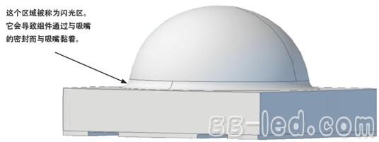
Figure 2 LED schematic
In addition to the appropriate nozzle settings, it is recommended that the user maintain and clean the nozzles on a regular basis based on the operating requirements of the motor system.
Electric Grill,Electric BBQ Grill,Portable Barbecue Grill,Electric Barbecue
Shaoxing Haoda Electrical Appliance Co.,Ltd , https://www.zjhaoda.com