introduction
Power supply as the power supply equipment for all electronic products, in addition to the performance to meet the requirements of power supply products, its own protection measures are also very important, such as overvoltage, overcurrent, overheat protection. Once the electronic product fails, such as when the input side of the electronic product is short-circuited or the output side is open, the power supply must be turned off its output voltage to protect the power MOSFET and the output side equipment from being burnt, otherwise it may cause further damage to the electronic product, or even It causes electric shock and fire of the operator. Therefore, the overcurrent protection function of the switching power supply must be perfected.
1 Overcurrent protection method commonly used in switching power supplies
Overcurrent protection has many forms, as shown in Figure 1, it can be divided into rated current drooping type, that is, フ type; constant current type; constant power type, most of which is current drooping type. The set value of the overcurrent is usually 110% to 130% of the rated current. Generally it is automatic recovery type.
In Fig. 1, 1 indicates a current droop type, 2 indicates a constant current type, and 3 indicates a constant power type.

Figure 1 Overcurrent protection characteristics
1.1 Current limiting circuit used in transformer primary direct drive circuit
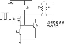
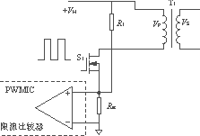
In the design of a circuit that is directly driven by the transformer (such as a single-ended forward converter or a flyback converter), it is relatively easy to achieve current limiting. Figure 2 is two ways to achieve current limiting in such a circuit.
The circuit of Figure 2 can be used for single-ended forward converters and flyback converters. In Figure 2(a) and Figure 2(b), a current limiting resistor Rsc is connected in series with the source of the MOSFET. In Figure 2(a), Rsc provides a voltage drop to drive transistor S2 on, in Figure 2(b). The current-limit voltage comparator connected across the Rsc can short-circuit the drive current pulse to provide protection when an overcurrent occurs.
Figure 2(a) compares with Figure 2(b), Figure 2(b) protects the circuit faster and more accurately. First, it presets the threshold voltage of the current-sense drive of the comparison amplifier to a more precise range than the threshold voltage Vbe of the transistor. Second, it takes the preset threshold voltage sufficiently small, and its typical value is only 100mV~ 200mV, therefore, the value of the current-limiting sampling resistor Rsc can be made smaller, thus reducing power consumption and improving the efficiency of the power supply.

(a) Transistor protection

(b) Current limiting comparator protection
Figure 2 Current limiting circuit in a single-ended forward or flyback converter circuit
When the AC input voltage varies from 90 to 264V and the output is equal, the peak currents of the transformers are greatly different, resulting in severe drift of the high and low-side overcurrent protection points, which is not conducive to the consistency of the overcurrent points. A pull-up resistor R1 from +VH is added to the circuit for the purpose of making the base of S2 or the non-inverting comparator of the current-limit comparator have a pre-value to achieve the highest possible consistency of the high- and low-side overcurrent protection points.
1.2 Current limiting circuit for base drive circuit
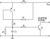
In general, the base drive circuit is used to isolate the control circuit of the power supply from the switching transistor. The output portion of the converter is common to the control circuit. The current limiting circuit can be directly connected to the output circuit, and its circuit is shown in FIG. In Figure 3, the control circuit is co-located with the output circuit. The working principle is as follows:

Figure 3 is used in current limiting circuits in a variety of power converters
When the circuit is working normally, the voltage drop generated by the load current IL flowing through the resistor Rsc is not enough to make S1 turn on. Since S1 is off when IC1=0, the capacitor C1 is in an uncharged state, so the transistor S2 is also turned off. If the current on the load side increases, so that IL reaches a set value such that ILRsc = Vbe1 + Ib1R1, then S1 is turned on, charging capacitor C1, its charging time constant Ï„ = R2C1, and the voltage after C1 is full of charge is VC1 = Ib2R4 + Vbe2. In order for the capacitor C1 to discharge quickly when the circuit detects an overcurrent, R4 should be selected.
1.3 Current limiting circuit without power loss
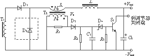
The above two types of overcurrent protection are more effective, but the presence of Rsc reduces the efficiency of the power supply, especially in the case of high current output, the power consumption on the Rsc is significantly increased. The circuit of Figure 4 uses current transformers as the detection components, which creates certain conditions for the improvement of power efficiency.
The circuit of Figure 4 works as follows: The current transformer T2 is used to monitor the load current IL. When passing through the primary of the transformer, the IL couples the change in current to the secondary, creating a voltage drop across the resistor R1. Diode D3 rectifies the pulse current, and after rectification, smoothing is filtered by resistor R2 and capacitor C1. When an overload occurs, the voltage across the capacitor C1 increases rapidly, causing the Zener D4 to conduct, the drive transistor S1 to conduct, and the S1 collector signal can be used as the drive signal for the power converter regulation circuit.

Figure 4 no power current limiting circuit
The current transformer can be wound with a ferrite core or an MPP toroidal core, but it has to be tried and tested to ensure that the core is not saturated. The ideal current transformer should reach the turns ratio is the current ratio. Usually, the transformer has Np=1, Ns=NpIpR1/(Vs+VD3). The specific winding data is finally adjusted experimentally to achieve the best performance.
Dc Gear Motor,Geared Motor,Dc Gear Motor 12V,Low Speed Gear Motor
Changzhou Sherry International Trading Co., Ltd. , https://www.sherry-motor.com