ARM (Advanced RISC Machines) is a generic term for a class of microprocessors. ARM is a well-known enterprise in the microprocessor industry. It designs a large number of high-performance, low-cost, low-power RISC processors, related technologies and software. The ARM microprocessor is a high performance, low power 32-bit microprocessor that is widely used in embedded systems. ARM 9 represents the mainstream processor of ARM, and has been widely used in handheld phones, set-top boxes, digital cameras, GPS, personal digital assistants and Internet devices. Here, the hardware of the data acquisition and transmission system in the ARM-based solar power generation system is completed by using the typical STR912FW44X6 chip in the ARM 9 series produced by ST as the MCU of the hardware development platform, and a RS 485 serial port is proposed. A new method of communication in place of the RS 232 string 121.
l hardware overall design framework
The overall hardware design framework is shown in Figure 1.
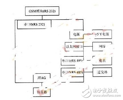
Figure 1 hardware overall design framework
2 Hardware introduction
Now with STR912FW44X6 chip as the hardware development platform MCU, STR912FW44X6 expands the dot matrix LCD display, input button, UART interface, IrDA, CAN, USB, ETM interface, audio amplifier / microphone amplifier and Ethernet interface. Among them, this article uses a UART interface and an Ethernet interface. The UART interface is divided into an RS 232 serial port and two RS 485 serial ports. RS 232 serial port is used to connect with RS 232 serial port of GSM module to realize wireless transmission of GPRS; two RS 485 serial ports, one for MODBUS communication interface and the other for power meter to collect statistics and display The amount of electricity generated by solar power systems. Ethernet is connected to the network through a network cable for wireless transmission of data.
3 hardware circuit design and function realization
3.1 RS 232 serial port circuit design and function realization
RS 232 is a serial data interface standard and is the most commonly used serial interface standard for data transmission between computers and computers, between computers and peripherals. The RS 232 serial interface bus is suitable for communication distances between devices up to 15 m and transmission rates up to 20 KB/s.
The RS 232 serial port is realized by the ST3232EAR produced by ST. ST3232EAR is a chip that converts the computer's serial port RS 232 signal level (-lO V, +10 V) to the TTL signal level (OV, +3.3 V) used by the microcontroller. Its internal structure consists of three parts: the first part is the charge pump circuit, which consists of 1 to 6 feet and 4 capacitors. Its function is to generate two power supplies of +12 V and -12 V to provide level for the RS 232 serial port. The second part is the data conversion channel, which consists of 7 to 14 legs and 2 data channels. Among them, 13 feet (RlIN), 12 feet (R1OUT), 11 feet (TlIN), 14 feet (T1OUT) are the first data channel; 8 feet (R2IN), 9 feet (R2OUT), 10 feet (T2IN), 7 The foot (T2OUT) is the second data channel. TTL/CMOS data is converted from TlIN, T2IN input to RS 232 data, from T1OUT, T20UT to computer DP9 plug; DP9 plug RS 232 data is converted from RlIN, R2IN input to TTL/CMOS data, and output from R1OUT, R2OUT. The third part is the power supply, which consists of 15-pin GND and 16-pin VCC (+5 V).
By connecting the RXD and TXD of the GPIO in the MCU to the 12-pin (R1OUT) and 11-pin (T1IN) of the ST3232, respectively, the 14-pin (T10UT) and the 13-pin (R1IN) output the RS 232 level, and then connect the GSM module RS 232. The serial port and the RS 232 serial port on the MCU board can achieve the purpose of controlling the function of the GSM module by writing an AT command to the RS 232 interface to realize data transmission via GPRS.
3.2 RS 485 serial port circuit design and function realization
RS 485 is used to collect data from solar power systems. The reason why RS 485 is used instead of RS 232 is because RS 485 has many advantages over RS ​​232. RS 232 adopts unbalanced transmission mode, that is, single-ended communication, and the data signals of the transceiver end are relative to the ground signal. Therefore, its common mode rejection is poor, coupled with the distributed capacitance of the twisted pair, the transmission distance is up to about 15 m, the maximum rate is 20 KB / s, and it can only support point-to-point communication. RS 485 adopts balanced transmission and differential acceptance to realize communication. Since the transmission line usually uses twisted pair and sometimes differential transmission, it has strong anti-common-mode interference capability, and the sensitivity of the bus transceiver is very high, and can be detected as low as 200. The voltage of mV, so its transmission signal can be recovered above km. RS 485 has a maximum communication distance of about 1 219 m and a maximum transmission rate of 10 MB/s. It uses dual-duplex operation to support multi-point data communication. The bus generally supports up to 32 nodes.
The RS 485 interface chip uses ADM3485. ADM3485 uses a single power supply +3.3 V operation, half-duplex communication mode, can complete the function of converting TTL level to RS 485 level. The structure and pins of the ADM34185 chip are very simple. The internal one contains a driver and a receiver. The RO and DI terminals are the output of the receiver and the input of the driver. When connected to the MCU, it only needs to be separately connected to the RXD and TXD of the MCU. Connected. The RE and DE terminals are the enable and receive terminals respectively. When RE is logic 0, the device is in the receiving state. When DE is logic 1, the device is in the transmitting state. Because ADM3485 works in half-duplex state, only You can control these two pins with one pin of the microcontroller. The A and B terminals are the differential signal terminals for receiving and transmitting respectively. When the level of the A pin is higher than B, it means that the transmitted data is 1; when the level of A is lower than the B terminal. The data sent by the representative is O. The wiring is very simple when connected to the MCU, only one signal is needed to control the reception and transmission of the ADM3485. At the same time, a matching resistor is added between the A and B terminals, and a 100 Ω resistor is generally selected. The design has two RS 485s, one for the MODBUS communication interface and the other for the watt-hour meter to collect statistics and display the amount of power generated by the solar power system.
3.3 Ethernet circuit design and function realization
The Ethernet network port uses 0880-1X1T-01, and the Ethernet physical layer interface chip uses ST's STElOOP Fast Ethernet physical layer chip. The STEl00P Ethernet interface chip provides a set of media independent interfaces (MII). Media independence refers to the fact that any type of PHY device can function without redesigning or replacing the MAC hardware. The MII interface is the standard interface between the Fast Ethernet MAC layer and the PHY layer and is the standard for the Ethernet industry defined by IEEE 802.3. It includes a data interface and a management interface between the MAC and the PHY. The data interface includes two separate channels for the transmitter and receiver, respectively. Each channel has its own data, clock, and control signals. The MII data interface requires a total of 16 signals. The management interface is a dual signal interface: one is the clock signal and the other is the data signal.
Through the management interface, the upper layer monitors and controls the PHY. Ethernet-based TCP/IP communication enables the ARM to be networked via a network cable and communicate with the computer in real time to transmit real-time data from the solar power system.
A new method of using RS 485 serial port instead of RS 232 serial port for communication is proposed. This method solves the limitation of the transmission distance and the number of nodes of the RS 232 serial port, and greatly improves the data transmission capability.
Commercial electric LED emergency double heads light is perfect for applications requiring a dependable, long lasting, energy efficient life safety solution with a traditional design. The twin heads emergency light is designed with injection-molded, flame-retardant, high impact thermoplastic housing .The adjustable heads allow for optimal lighting of the path of egress.

Emergency Exit Lights,2 Head Emergency Light,Twin Spot Emergency Light,Led Twin Spot Emergency Lights
Jiangmen City Pengjiang District Qihui Lighting Electrical Appliances Co., Ltd , https://www.qihuilights.com