By the way, share a few tools website for everyone:
HEX/string conversion
JSON check
BASE64 encoding / decoding
OTAA mode access step preparationBefore the OTAA is connected to the network, the node needs to have three parameters:
APPEUI node custom 8-byte long address
Both the APPKEY server and the node are saved in advance for encryption and decryption of the Join_acept message.
DevNonce 2-byte random number used to generate random AppSKey and NwkSKey
These parameters can be fixed in the program through the program, or through the serial port or other means to tell the node before the network operation.
When these preparations are done, the node device will be able to access the network.
first step
1.node initiates a network request, that is, sends a join_request message.
According to the LoRaWAN specification, the format of the join_request message is as follows:
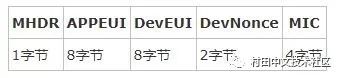
among them

Note that the Join_request message is unencrypted.
Second step
2.GW uploads this data to NS
The GW does not parse the data of the MAC layer, but directly performs base64 encoding, and then encapsulates it into a JSON packet and uploads it to the NS. The data of the MAC layer is located at rxpk.data.
Sample data:
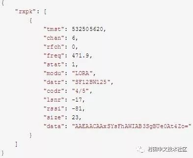
Here, the base64 decoding of data, we can see the MAC layer data, because the join_request message data is unencrypted.
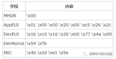
The contents of the data section are as follows:
\x00 \x01 \x00 \x00 \x20 \x00 \xc5 \x26
\x2c \x16 \x10 \x16 \x20 \x00 \x77 \x4a
\x00 \x54 \x7b \x40 \x2d \xe1 \x9a
The contents of each part are:
third step
3. NS sends the device into the network packet to the AS.
Sample data:
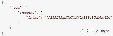
The base64 is decoded by the base.frame, and the content is:
\x00 \x01 \x00 \x00 \x20 \x00 \xc5 \x26
\x2c \x16 \x10 \x16 \x20 \x00 \x77 \x4a
\x00 \x54 \x7b \x40 \x2d \xe1 \x9a
It can be seen that the data data of the original MAC layer has not changed.
the fourth step
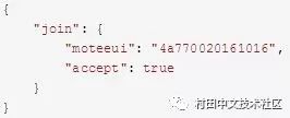
4.AS agrees to join the network and replies to the NS to agree to the network.
Sample data:
the fifth step
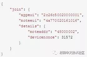
5.NS generates MoteAddr and sends the information of node to AS.
Sample data:
Step 6
6.AS generates a key and tells NS about the relevant information.
Sample data:
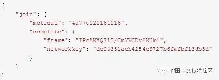
It can be seen that the networkkey is sent directly to the NS, which is NwkSKey. The reason why the plain text is told to NS is because:
1. NS does not do the decryption work, so it cannot be decrypted by APPKEY.
2.networkkey will be used when NS checks the uplink and downlink data.
Seventh step
7.NS tells GW the data, and GW converts it into a MAC packet and sends it to node.
Sample data:
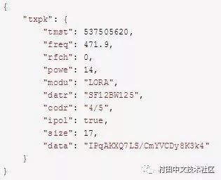
It should be noted that the data part at this time is base64 encoded and AES encrypted, directly decoded, the data seen is invalid, need to be decrypted again, decryption needs to use APPKEY, which is the APPKEY introduced earlier.
The txpk.data part is the join_accept message of LoRaWAN MAC.
Eighth step
8.node parses the join_accept message section
According to the LoRaWAN specification, the format of the join_accept message is as follows:
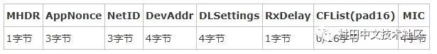
among them
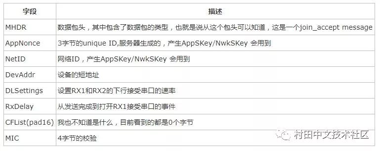
Note that the Join_accept message is encrypted and needs to be decrypted using APPKEY.
Txpk.data:"data": "IPqAKXQ7LS/CmYVCDy8K3k4"
Base64 decoding: \x20 \xfa \x80 \x29 \x74 \x3b \x2d \x2f\xc2 \x99 \x85 \x42 \x0f \x2f \x0a \xde\x4e
This data is not decrypted, we still need to decrypt
After decryption, it is \x20 \x43 \x75 \xcb \x24 \x00 \x00 \x02\x00 \x00 \x48 \x03 \x00 \x82 \xc9 \xd0\xf9
The specific situation is as follows:
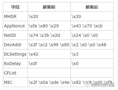
It can be seen that DevAddr is 0x48000002, and AppSKey and NwkSKey cannot be directly seen, and need to be recalculated.
Calculated as follows:
NwkSKey = aes128_encrypt(AppKey, 0x01 | AppNonce | NetID | DevNonce | pad16)
AppSKey = aes128_encrypt(AppKey, 0x02 | AppNonce | NetID | DevNonce | pad16)
GALOCE Multi-axis Load Cell offers 0-10N / 0-20N /0-30N / 0-50N four rated measuring ranges for all three axes, each axis supports both tension and compression force measurement. 3-axis Force Sensor adopts independent wheatstone full bridge for each axis to deliver mV/V output proportional to the applied force and requires no mathematical manipulation. Typical applications for this type of transducer are for example friction force measurement, force control in robotics, force monitoring in handing devices, industrial test benches,etc..
Multi-component force sensor,Multi Axis Load Cell,multicomponent transducer,3 Axis Load Cell
GALOCE (XI'AN) M&C TECHNOLOGY CO., LTD. , https://www.galoce-meas.com