BATTERY MANAGEMENT SYSTEM, commonly known as battery nanny or battery housekeeper, is an important link between vehicle power battery and electric vehicle. Its main functions include: real-time monitoring of battery physical parameters; battery state estimation; online diagnosis and early warning; Discharge and precharge control; balance management and thermal management. The battery management system (BMS) is mainly to improve the utilization of the battery, prevent overcharging and overdischarging of the battery, prolong the service life of the battery, and monitor the state of the battery.
The battery management system not only has close contact with the battery, but also has various links with the whole vehicle system. Among all the faults, the fault of the battery management system is relatively high and difficult to handle compared with other systems. This paper summarizes some common methods for dealing with battery management system failures and case analysis of common faults in battery management systems for reference by vehicle, battery, and management system manufacturers.
BMS failure analysis method
Observation
When the communication interruption or control abnormality occurs in the system, observe whether each module of the system has an alarm, whether there is an alarm icon on the display, and then check the obtained phenomenon one by one.
Fault recovery method
The faults of the vehicle under different conditions are different . When conditions permit, the faults are reproduced under the same conditions as much as possible, and the problem points are confirmed.
Exclusion
When similar interference occurs in the system, each component in the system should be removed one by one to determine which part affects the system.
Replacement method
When a module experiences abnormalities such as temperature, voltage, and control, change the module position of the same number of strings to diagnose a module problem or a harness problem.
Environmental inspection
When the system fails, if the system can't display, we should not rush to consider it in depth, because we often ignore some details. First of all, we should look at the obvious things: if there is no power? Is the switch turned on? Are all the connections connected? Perhaps the root of the problem lies in it.
Program upgrade method
When the new program is burned, an unclear fault occurs, resulting in abnormal system control. The previous version of the program can be burned to compare and analyze the fault.
Data analysis
When the BMS is controlled or related to faults, the BMS stored data can be analyzed to analyze the contents of the message in the CAN bus.
Common fault case analysis
1. The entire system does not work after the system is powered.
Possible Causes
Abnormal power supply, short-circuit or open circuit harness, DCDC no voltage output
Troubleshooting

2 , BMS can not communicate with the ECU
Possible Causes
BMU ( master module) is not working, CAN signal line is broken
Troubleshooting
Check if the BMU 's power supply 12V/24V is normal; check whether the CAN signal transmission line is retracted or the plug is not inserted; if the CAN port data is monitored , whether it can receive the BMS or ECU data packet.
3 , BMS and ECU communication is unstable
Possible Causes
Bad external CAN bus, bus branch is too long
Troubleshooting
Check if the bus matching resistor is correct; if the matching position is correct and the branch is too long.
4 , BMS internal communication is unstable
Possible Causes
The communication line plug is loose, the CAN trace is not standardized, and the BSU address is duplicated. Troubleshooting
Check if the wiring is loose; check if the bus matching resistance is correct, if the matching position is correct, and if the branch is too long; check if the BSU address is duplicated.
4 , insulation detection alarm
Possible Causes
The battery or driver is leaking. The insulation module detection line is connected incorrectly.
Troubleshooting Use the BDU display module to view the insulation test data, check the battery bus voltage, and whether the negative bus to ground voltage is normal. Use the insulation shaker to measure the insulation resistance of the bus and driver to ground.
5 , the main relay does not pick up after power-on
Possible Causes
The load detection line is not connected, the pre-charge relay is open, and the pre-charge resistor is open. Troubleshooting
Use the BDU display module to view the bus voltage data, check the battery bus voltage, and whether the load bus voltage is normal; check whether the load bus voltage rises during the precharge process.
6 , the acquisition module data is 0
Possible Causes
The collection module of the acquisition module is disconnected and the acquisition module is damaged.
Troubleshoot and re-plug the module wiring, measure the battery voltage at the acquisition line connector, and measure the resistance at the temperature sensor cable plug.
7 , battery current data error
Possible Causes
Hall signal line plug is loose, Hall sensor is damaged, and the acquisition module is damaged.
Troubleshoot and re-plug the current Hall sensor signal line; check if the Hall sensor power supply is normal and the signal output is normal; replace the acquisition module.
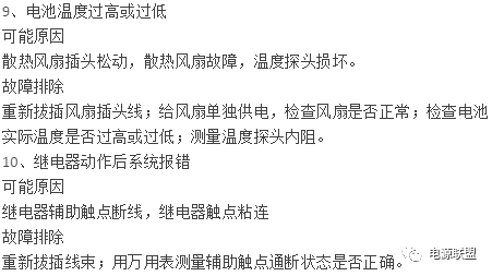
8 , the battery temperature difference is too large
Possible Causes
The cooling fan plug is loose and the cooling fan is faulty.
Troubleshoot and re-plug the fan plug cable; separately supply power to the fan and check if the fan is normal.


11 , can not be charged using a charger
Possible Causes
The charger is not communicating properly with the BMS.
Troubleshooting
Replace a charger or BMS to confirm if the BMS is faulty or the charger is faulty; check that the matching resistance of the BMS charging port is normal.
12 , the vehicle instrument has no BMS data display
Possible Causes
The main control module harness connection is abnormal.
Troubleshooting
Check whether the main control module harness is fully connected, whether there is a normal low voltage working voltage of the car, and whether the module works normally.
13. The detection data of some battery cases is lost.
Possible Causes
Some parts of the vehicle may be in poor contact, or the BMS slave module may not work properly.
Troubleshooting
Check the connector contact or replace the BMS module.
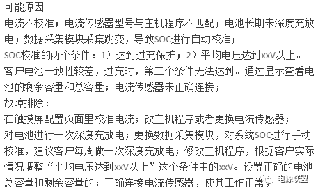
14 , SOC anomaly
Phenomenon: SOC changes greatly during system operation, or repeatedly jumps between several values; in the system charging and discharging process, SOC has a large deviation; SOC always shows a fixed value.


Oil Filter For ISUZU
ISUZU Oil Filter Replacement,Oil Filter For ISUZU Cars,ISUZU Car Oil Filter,ISUZU Auto Oil Filter
Zhoushan Shenying Filter Manufacture Co., Ltd. , https://www.renkenfilter.com