Answer: The image signal and audio signal of color TV are generally divided into audio and video signal (ie AV signal) and carrier frequency signal (ie modulated high frequency signal). The audio and video signal cannot be transmitted over long distance, so it must be Modulated to a higher frequency carrier signal can be transmitted through a long-distance transmission line or transmitting antenna.
The reason why audio and video signals cannot be transmitted over long distances can be explained as follows: when the transmission distance is very long, the length of the transmission line is already comparable to the wavelength of the signal. At this time, the voltage or current value of each point on the transmission line is different. When the voltage at the input terminal is the maximum value, the voltage at the farthest end of the transmission line is not necessarily the maximum value, and may be the minimum value or the negative maximum value. For example, when the voltage at the input is at the maximum, the voltage at the transmission line is exactly equal to half the wavelength, and the voltage is at the negative maximum. Because the maximum voltage at the input has not been transmitted, it takes half a cycle to reach it, and the current detected voltage is exactly the negative maximum voltage input in the first half of the cycle time. And this situation happens only when the transmission line is already in a stable working state, which means that the transmission line has entered the charging and discharging state.
When the voltage at the input terminal is the maximum value, if the transmission line has not been charged, that is, the transmission line has not input any voltage before, the voltage on all other places on the transmission line is zero, and the signal will be transmitted after a period of time. The longer the transmission line, the longer the time to wait for the signal to arrive. Therefore, the various impedances or loads connected on the transmission line cannot be simply regarded as parallel, because each load is not connected to the input signal at the same time. Therefore, the calculation of the transmission line impedance is very complicated, and it is only good when the signal is stable.
When a signal is input to the transmission line, the signal previously input to the transmission line will also be superimposed with the current input signal, because the signal at the far end of the transmission line is also doing two-way movement, and the current is like flowing water. , So the current at a certain point on the transmission line will always run forward because of the change in the polarity of the input voltage, and then run back again. Therefore, the signal is transmitted on the transmission line according to the principle of charging and discharging of the capacitor and the inductor. We can think of the transmission line as being composed of many inductors connected in series and many capacitors connected in parallel, so that the signals needed for transmission on the transmission line The process that the time and the phase of each point on the transmission line are different is expressed. It can be seen that the voltage phase of each point on the long-distance transmission line is different from the phase of the input signal, and only when the signal transmitted on the transmission line is a regular set of signals (such as the fundamental wave), each point on the transmission line The phase of the voltage can be relatively consistent with the input signal (behind a phase) to change.
High-frequency signals will oscillate when they are transmitted on a transmission line of limited length, that is, the old and new signals will superimpose and generate standing waves. The most special case is a standing wave generated by a quarter-wavelength short-circuit line or an open route. The quarter-wavelength short-circuit line is equivalent to an open circuit and can be equivalent to a parallel oscillation circuit; the quarter-wavelength open circuit is equivalent to a short circuit and can be equivalent to a series oscillation circuit. Only when the high-frequency signal is transmitted on an infinitely long transmission line or when the terminal load can completely absorb the input signal, the transmission line will not oscillate, that is, the traveling wave. This situation is called matching.
The so-called standing wave can be likened to grabbing a long rope in your hand and swinging it up and down, and one end of the rope is fixed to the wall. As a result, when you look at it from the side, you can see many peaks and many valleys, and they The position is fixed, this phenomenon is called standing wave; if you untie the other end of the rope and let it move freely, what you see is another scene. When you swing the rope with your hand, the rope produces The wave crest will move like a wave, this phenomenon is called traveling wave.
Audio and video signals are difficult to transmit over long distances in the transmission line, because the audio and video signals are not a set of regular signals, and there is no wavelength in the transmission line. Although the audio and video signals also have amplitude superposition in the transmission line, they are not Superimposed oscillations will occur, and this amplitude superposition will produce severe phase and amplitude distortions.
In addition, audio and video signals are generally not symmetrically distributed on the time axis with high and low levels, so its average value is not necessarily zero, and the average DC level is not a fixed value. This signal is transmitted over a long distance in the transmission line. In addition to attenuation, the phase and amplitude distortions are more serious, and the DC level will have an electrolytic effect (with air) on the transmission line, making the connectors poorly connected.
Therefore, the audio and video signals must be modulated by high frequency to make it become a high frequency AC signal with an average value equal to zero before long-distance transmission. After the high-frequency modulation of the audio and video signal, the relative bandwidth of the signal is very small. Basically, the modulated carrier can be regarded as a single frequency signal. Therefore, the transmission amplitude and phase distortion in the transmission line are very small. The transmission line is equivalent to only Produce delay and attenuation effects. In addition, the higher the carrier frequency is selected, the greater the number of channels for transmitting signals. The propagation speed of the carrier signal in the transmission line is related to the distribution parameters of the transmission line, which is generally about 200,000 kilometers, which is two-thirds of the light wave.
Audio and video signals cannot be transmitted through the antenna. The general antennas are half-wave dipole antennas (that is, the length of the antenna is exactly half a wavelength). The characteristics of the half-wave dipole antenna and the quarter-wavelength open route are basically similar, quite For series resonance. But where the antenna differs from the quarter-wavelength open route, the antenna is open, and the quarter-wavelength open route is centralized.
When the antenna is fully charged (an extreme case, analysis of ⊿t at a certain time), it can be regarded as a capacitor with the polar plate opened, and the half-wave oscillator is equivalent to the two polar plates of the capacitor. The electric charge distributed on the board will generate an electrostatic field, which will induce the receiving antenna at a distance, so that the receiving antenna is also charged; when the antenna is charged, the current flows through the antenna, and the antenna is equivalent to a wire. A magnetic field will be generated around the wire, and this magnetic field will also induce the remote receiving antenna to generate an induced electromotive force. This can be clearly understood by considering the two antennas as the primary and secondary of the transformer.
The antenna works like a series-parallel resonant circuit composed of inductance and capacitance. It only resonates to a certain frequency signal. The audio and video signal is not a single frequency signal, so it will not resonate in the antenna loop, so it cannot Transmission by radio. The propagation speed of the carrier wave in the air is less than the speed of light but very close to the speed of light.
At present, China's TV broadcasting mainly uses the meter wave band (VHF) and decimeter wave band (UHF), and is developing the centimeter wave band (UHF SHF), and the microwave band (UK) is mainly used for satellites. broadcast. The current standard of analog TV signals in China is:
1) The image carrier frequency signal is transmitted by the residual sideband, and the nominal bandwidth of the residual sideband is 0.75MHz.
2) The local oscillation frequency of each channel is always 38 MHz higher than the image carrier frequency and 31.5 MHz higher than the audio carrier frequency.
3) The lower limit of the channel bandwidth is always 1.25 MHz lower than the image carrier frequency, and the upper limit is always 0.25 MHz higher than the audio carrier frequency.
4) The sound carrier frequency of each channel is always 6.5MHz higher than the image carrier frequency.
5) 92 ~ 124 MHz and 566 ~ 606 MHz are the bands used for public FM broadcasting and radio wave communication, etc. TV channels are not arranged.
6) The center frequency of each channel and the corresponding center wavelength are the parameters to estimate the antenna size and debug the TV.
Modulation and demodulation are the transmission and reception processes of color TV image signals and sound signals. Modulation mainly refers to TV broadcasting stations, and demodulation mainly refers to color TV receivers. The main task of the color TV receiver is to restore the high-frequency color TV signal received by the antenna through a series of amplification, transformation and decoding processes to restore the three primary color image signals, and finally reproduce the original image on the fluorescent screen of the color picture tube. Acoustic sound is reproduced from the speaker.
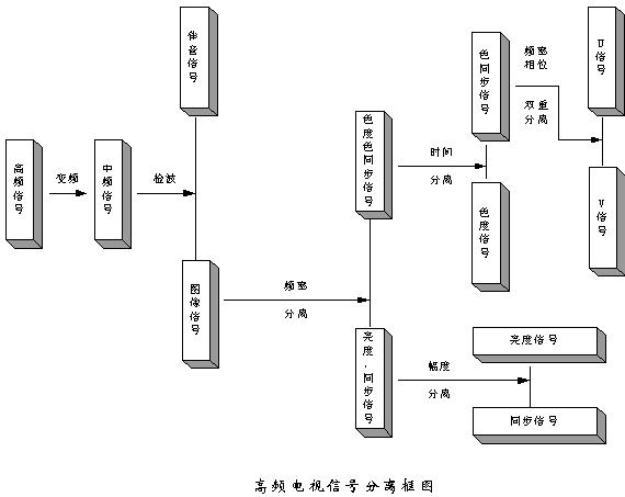 |
The radio frequency TV signal received by the color TV antenna is first amplified by a VHE / UHF tuned amplifier; then it is mixed with the local oscillation and converted into an intermediate frequency TV signal with an image intermediate frequency of 38MHz and a sound intermediate frequency of 31.5MHz (center The frequency is about 35MHz). From the perspective of the spectrum structure, it is equivalent to relocating the input signal carrier frequency to another lower fixed frequency, but it is still a high-frequency modulated signal. The intermediate frequency signal is selected by the surface acoustic filter to be amplified by the intermediate frequency amplifier, and after further screening, it is subjected to amplitude limiting and synchronous detector detection, and then a luminance signal of 0 ~ 6MHz and a chrominance signal of subcarrier frequency of 4.43MHz are output (Quadrature Amplitude Modulation), and the second audio intermediate frequency signal (frequency modulation) with a carrier frequency of 6.5 MHz.
The sound signal (6.5MHz) adopts the frequency modulation method, and is separated from the image signal (0 ~ 6MHz) in the frequency domain, so that the sound signal can be taken out through the 6.5MHz bandpass filter, and then passed through the sound mid-range and frequency discrimination , You can restore the sound signal (audio), and then through the power amplifier and speakers, and finally restore it to sound. At the same time, in order to prevent the sound signal from interfering with the image, a 6.5MHz notch filter must also be used to absorb the sound signal in the video image signal channel. The remaining signals are the brightness signal and the color signal (two orthogonally modulated color difference signals). The signal is divided into three outputs, one brightness signal (Y), one color signal (V, U), and one line sync signal.
The first way, output to the brightness channel. The sound and color subcarrier signals are absorbed by the 6.5MHz and 4.43MHz traps to eliminate the light spot interference caused by the sound signals and chrominance subcarrier signals, and then the brightness signal is taken out, but the brightness signal is absorbed by the interference signal multiple times After the high-frequency component is also lost, it will affect the clarity. For this reason, the brightness signal generally has to be processed by a differential circuit, which is also called a hook circuit. After the brightness signal is processed by the differential circuit, the high-frequency component is greatly improved, so that the outline of the displayed image becomes clearer. Because the color signal must be demodulated to obtain the color difference signal, this process also requires a certain amount of time. In order for the brightness signal and the color difference signal to reach the matrix circuit at the same time, the brightness signal must be delayed by 0.6us, and then the brightness signal Add or subtract two color difference signals, and finally output red R, green G, and blue B signals.
The second channel is output to the chroma channel. Firstly, it is amplified by a 4.43MHz band-pass amplifier to remove the luminance signal, and the chrominance signal and color burst signal are taken out; after the color burst separator, the color burst signal is further separated from the chrominance signal. The separated color burst signal, on the one hand, controls the phase detector to make the subcarrier generation circuit of this machine work synchronously, on the other hand, it controls the color recognition, achromatic detection circuit, etc. The separated chrominance signal is amplified by a chrominance amplifier, and then sent to a comb filter to decompose the chrominance signal into two components, Fu and Fv. At the same time, the phase error “electric average†of the two lines is processed by line inversion. Eliminate hue distortion caused by phase error. Then send them to (RY) and (BY) synchronous detectors respectively, demodulate the red difference signal (RY) and the blue difference signal (BY), and then send them to the matrix circuit to add or subtract the brightness signal, and finally Output three primary color signals of red, green, and blue, and finally output to the three cathodes of the color picture tube through video amplification, and modulate the current of the three electron beams to reproduce the color image.
The third way, output to the scan synchronization separation circuit. Take out the line and field composite synchronization signal, take out the synchronization pulse signal from the differential circuit and send it to the phase detector to detect the phase, turn the phase error into a voltage error signal, and the voltage error signal controls the voltage-controlled oscillator (also called phase-locked loop oscillator) ) To force the line oscillation frequency and phase to be synchronized with the input signal. The other (multi-pulse) synchronization signal is integrated by an integrator to obtain a field synchronization signal whose output voltage amplitude is proportional to the number of input pulses. This field synchronization signal then controls the oscillation phase of the field oscillator to make the field frequency equal to The field synchronization signal is consistent.

Follow WeChat

Download Audiophile APP

Follow the audiophile class
related suggestion
'+ data.data.username +' '; dom + ='
App Control Window Cleaning Robot
China Window Washing Robot , Glass Cleaning Robot ,Automatic Window Cleaner Robot,App Control Window Cleaning Robot, we offered that you can trust. Welcome to do business with us.China window clean robot manufacture and big supplier, best quality and good price.
2019 APP Window Clean Robot ,smart clean robot. Window Cleaning Robot Video welcome to see our youtube.

if you have any require window cleaning robot wireless,please let me know,thanks
App Control Window Cleaning Robot
Window Washing Robot,Glass Cleaning Robot,Automatic Window Cleaner Robot,App Control Window Cleaning Robot,Window Cleaning Robot Video
Zhengzhou Bangmi Smart Technology Co., Ltd. , https://www.globalcleanrobot.com