5.1 Link budget
Both uplink and downlink have their own transmit power loss and path fading. In cellular communications, in order to determine the effective coverage, the maximum path fading, or other limiting factors must be determined. On the uplink, the limiting factor from the mobile station to the base station is the base station's acceptance sensitivity. For the downlink, the main limiting factor from the base station to the mobile station is the base station's transmit power. By optimizing the balance relationship between uplink and downlink, it is possible to make the cell within a radius of coverage and have better communication quality.
Generally, by using base station resources, the link balance (uplink or downlink) of each cell in the network is improved, so that the system works in the best state. In the end, it can also promote better mobile call performance during handover and call establishment. Figure 5-01 is a base station link loss calculation, which can be used as a reference.
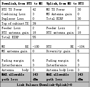
Figure 5-01
Calculation of uplink and downlink balance. For the GSM system that implements two-way communication, the uplink and downlink balance is very important. It is the main factor to ensure equal traffic volume and communication quality in both directions, and is also related to the actual coverage of the cell.
Downlink (DownLink) refers to the link sent by the base station and received by the mobile station.
Uplink (UpLink) refers to the link sent by the mobile station and received by the base station.
The algorithm for uplink and downlink balance is as follows:
Downlink (expressed in dB):
PinMS = PoutBTS-LduplBTS-LpBTS + GaBTS + Cori + GaMS + GdMS-LslantBTS-LPdown
In the formula:
PinMS is the power received by the mobile station;
PoutBTS is the output power of BTS;
LduplBTS is the loss of combiner, duplexer, etc .;
LpBTS is the loss of the feeder cables, jumpers and connectors of the BTS antenna;
GaBTS is the gain of the transmitting antenna of the base station;
Cori is the directional coefficient of the base station antenna;
GaMS is the gain of the receiving antenna of the mobile station;
GdMS is the diversity gain of the receiving antenna of the mobile station;
LslantBTS is the polarization loss of the dual-polarized antenna;
LPdown is the downlink path loss;
Uplink (expressed in dB):
PinBTS = PoutMS-LduplBTS-LpBTS + GaBTS + Cori + GaMS + GdBTS -LPup + [Gta]
In the formula:
PinBTS is the power received by the base station;
PoutMS is the output power of the mobile station;
LduplBTS is the loss of combiner, duplexer, etc .;
LpBTS is the loss of the feeder cables, jumpers and connectors of the BTS antenna;
GaBTS is the gain of the receiving antenna of the base station;
Cori is the directional coefficient of the base station antenna;
GaMS is the gain of the transmitting antenna of the mobile station;
GdBTS is the diversity gain of the base station receiving antenna;
Gta is the gain from using tower amplifier;
LPup is the upstream path loss.
According to the reciprocity theorem, for any mobile station location, the uplink path loss is equal to the downlink path loss, ie:
LPdown = LPup
Let the system margin be DL, the mobile station's deterioration reserve is DNMS, the base station's deterioration reserve is DNBTS, the mobile station's receiver sensitivity is MSsense, the base station's receiver sensitivity is BTSsense, and Lother is other losses, such as building penetration Loss, in-vehicle loss, human loss, etc. Therefore, for any point in the coverage area, it should meet:
PinMS-DL-DNMS-Lother> = MSsense
PinBTS-DL-DNMS-Lother> = BTSsense
The purpose of uplink and downlink balance is to adjust the transmit power of the base station so that the point on the boundary of the coverage area (the point farthest from the base station) meets:
PinMS-DL-DNMS-Lother = MSsense
Thus, the calculation formula of the maximum transmission power of the base station is obtained:
PoutBTS <= MSsense-BTSsense + PoutMS + GdBTS-GdMS + LslantBTS-Gta + DNMS-DNBTS
5.2 Determination of various types of losses
â—† Penetration loss of a building Penetration loss of a building refers to the attenuation of radio waves when it passes through the outer structure of a building. It is equal to the difference between the median field strength outside and inside the building.
The penetration loss of a building has a lot to do with the structure of the building, the types and sizes of doors and windows, and floors. The change of penetration loss with the height of the floor is generally -2dB / layer. Therefore, the penetration loss of the first layer (bottom layer) is generally considered.
The following is a set of data for the 900MHz frequency band, comprehensive foreign test results:
--- In general urban reinforced concrete frame buildings in medium-sized urban areas, the median penetration loss is 10dB and the standard deviation is 7.3dB; the suburban similar buildings have a median penetration loss of 5.8dB and a standard deviation of 8.7dB.
--- In general urban reinforced concrete frame buildings in metropolitan areas, the median penetration loss is 18dB and the standard deviation is 7.7dB; the suburban similar buildings have a median penetration loss of 13.1dB and a standard deviation of 9.5dB.
--- For a building with a metal shell structure or a special metal frame structure in a large urban area, the median penetration loss is 27 dB.
Since the urban environment in China is very different from abroad, it is generally 8--10dB higher than similar foreign names.
For 1800MHz, although the wavelength is shorter than 900MHz and the penetration capability is greater, the diffraction loss is greater. Therefore, in fact, the penetration loss of buildings at 1800MHz is greater than that at 900MHz. As mentioned in GSM specification 3.30, the penetration loss of buildings in urban environments is generally 15 dB, and 10 dB in rural areas. Generally, it is 5--10dB larger than the penetration loss of 900MHz in similar areas.
â—† Human body loss For the handheld, when it is located on the waist and shoulders of the user, the received signal field strength will be reduced by 4--7dB and 1--2dB respectively when the antenna is away from the human body by several wavelengths.
The general human loss is set to 3dB.
â—† In-vehicle loss The in-vehicle loss caused by a car with a metal structure cannot be ignored. Especially in economically developed cities, people spend part of their time in cars.
Generally, the loss in the car is 8-10dB.
◆ Feeder loss The 7/8 ″ feeder is often used in GSM900. At 1000MHz, the loss per 100 meters is 4.3dB; at 2000MHz, the loss per 100 meters is 6.46dB, which is more 2.16 dB.
5.3 Wireless propagation characteristics
| The propagation of mobile communication is shown in the curve in Figure 5-02. The overall average value decreases with distance, but the signal level experiences the effects of fast and slow fading. Slow fading is the reflection of the signal from the terrain around the receiving point, so that the signal level has a large change in the range of tens of meters. If the mobile station moves without any obstacles, the signal level is only The distance of the machine. So usually the signal level at a certain point refers to the average signal level in the range of tens of meters. The change in this signal is normally distributed. The standard deviation is different for different terrain features, usually around 6-8dB. Fast fading is superimposed on slow fading signals. The speed of this decline is very fast, up to dozens of times per second. In addition to the terrain and features, it is also related to the speed of the mobile station and the wavelength of the signal, and the amplitude is very large, which can be dozens of dB, and the change of the signal is Rayleigh distribution. Fast fading tends to reduce voice quality, so reserve for fast fading. | 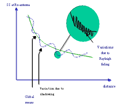 Figure 5-02 |
The propagation of radio waves in free space is the most basic and simplest one in the study of radio wave propagation. Free space is an ideal space that satisfies the following conditions: 1. Uniform and lossless infinitely large space, 2. Isotropics, and 3. Conductivity is zero. Application of electromagnetic field theory can be deduced that under free space propagation conditions, the expression of the transmission loss Ls is:
Ls = 32.45 + 20lgf + 20lgd
Free space basic transmission loss Ls is only related to frequency f and distance d. When f and d are doubled, Ls both increase by 6dB. From this, we can see that the propagation loss of the GSM1800 base station is 6 dB larger than that of the GSM900 base station in free space, as shown in Figure 5-03.
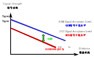
Figure 5-03
The main feature of land mobile channels is multi-path propagation. The actual multi-path propagation environment is very complicated. It is often simplified when studying propagation problems, and it starts with the simplest case. The two-path model that only considers the direct wave from the base station to the mobile station and the ground reflected wave is the simplest propagation model. The two-path model is shown in Figure 5-04. It can be derived by applying electromagnetic field theory. The expression of transmission loss Lp is: Lp = 20lg (d2 / (h1 * h2))
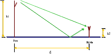
Figure 5-04
5.4 Two commonly used radio wave propagation models
â—† Okumura radio wave propagation attenuation calculation mode
GSM900MHz mainly uses the Okumura radio wave propagation attenuation calculation mode recommended by CCIR. This model uses the median field strength or path loss of a quasi-flat terrain metropolitan area as a reference, and other factors such as propagation environment and terrain conditions are corrected in the form of correction factors. The basic transmission loss on different terrains is separately predicted according to the following formula.
L (urban area) = 69.55 + 26.16lgf-13.82lgh1 + (44.9-6.55lgh1) lgd-a (h2) -s (a)
L (suburban) = 64.15 + 26.16lgf-2 [lg (f / 28)] 2-13.82lgh1 + (44.9-6.55lgh1) lgd-a (h2)
L (country road) = 46.38 + 35.33lgf- [lg (f / 28)] 2-2.39 (lgf) 2-13.82lgh1 + (44.9-6.55lgh1) lgd-a (h2)
L (open area) = 28.61 + 44.49lgf-4.87 (lgf) 2-13.82lgh1 + (44.9-6.55lgh1) lgd-a (h2)
L (forest area) = 69.55 + 26.16lgf-13.82lgh1 + (44.9-6.55lgh1) lgd-a (h2)
among them:
f ---- working frequency, MHz
h1 --- Base station antenna height, m
h2 --- Mobile station antenna height, m
d ---- distance to base station, km
a (h2) --- mobile station antenna height gain factor, dB
a (h2) = (1.1lgf-0.7) h2-1.56lgf + 0.8 (medium and small cities)
= 3.2 [lg (11.75h2)] 2-4.97 (large city)
s (a) --- density correction factor of urban buildings, dB;
s (a) = 30-25lga (5%
â—† Cost-231-Walfish-Ikegami radio wave propagation attenuation calculation mode
GSM 1800 MHz mainly uses the "Cost- 2-Walfish-Ikegami" radio wave propagation attenuation calculation mode recommended by the European Telecommunications Science and Technology Research. The characteristic of this mode is: a radio wave loss mode in a small area coverage obtained from the actual measurement of radio waves in many cities.
There are two cases of line-of-sight and non-line-of-sight:
(1) The basic transmission loss in line-of-sight is calculated using the following formula
L = 42.6 + 26lgd + 20lgf
(2) The basic transmission loss in non-line-of-sight situations is composed of three items:
L ï¼ Lo + Lmsd + Lrts
Lo = 32.4 + 20lgd + 20lgf
a) Lo stands for free space loss
b) Lmsd is the diffraction loss of multiple shields
c) Lrts is the diffraction and scattering loss from the roof to the street.
No matter which mode is used to predict wireless coverage, it is just an approximate calculation based on theory and test results statistics. Because the actual geographic environment is very different, it is difficult to accurately describe it with a mathematical model, especially in the dense streets of urban areas. The reflection, diffraction and blocking of buildings under the following rules bring great difficulties to the prediction of mathematical models. therefore. Although the prediction with a certain accuracy can play a preliminary role in guiding the selection and placement of network base stations, there is always a difference between the prediction and the actual signal field strength value through the mathematical model. Due to the complexity and variability of the mobile environment, it is quite difficult to accurately calculate the median of the received signal. The practice in wireless communication engineering is to find out the propagation loss (or received signal field strength) and distance, frequency and antenna under various terrain features on the basis of a large number of field strength tests, after data analysis and statistical processing High degree of relationship, giving various charts and calculation formulas of propagation characteristics, establishing a propagation prediction model, so that the median value of the received signal can be predicted by a simpler method.
5.5 Reference coverage standards
Indoor coverage level in the prosperous urban area of ​​large cities: -70dBm
General urban indoor coverage level: -80 dBm
Urban outdoor coverage level: -90 dBm
Rural: -94 dBm
Appendix 1: Dual-polarized 90 ° directional antenna

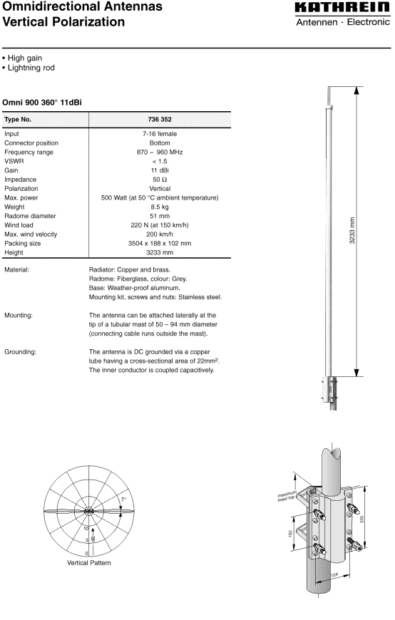
Appendix 2: Omni-directional antenna

Follow WeChat

Download Audiophile APP

Follow the audiophile class
related suggestion
