1 Introduction
This article refers to the address: http://
As a high-bandwidth, high-quality new Internet multimedia service, IPTV puts higher demands on telecom operators' IP metropolitan area networks. Compared with the traditional unicast technology, the multicast technology has the advantage that the network bandwidth does not increase linearly with the number of users on the basis of the same transmission efficiency, which can effectively save the load of the video server and the bearer network. Therefore, telecom operators need to deploy and implement IPTV services efficiently and economically. It is recommended to use end-to-end multicast push, and the configuration of IP multicast networks is the key.
At present, the telecom operator IP metropolitan area network is mainly composed of a metro backbone network and a broadband access network, and the IPTV service data is sequentially pushed to the user end through the metro backbone network and the broadband access network. The metro backbone network is mainly composed of network layer (layer 3) devices. It can enable multicast routing protocols such as PIM-SM to access the multicast source (that is, the IPTV head end device) to forward and forward multicast packets. The broadband access network is mainly composed of data link layer (layer 2) devices. It can use Layer 2 multicast forwarding such as IGMP Proxy or IGMP Snooping to access IPTV terminal equipment (ie, IPTV set-top box). Figure 1 is a schematic diagram of an IPTV end-to-end multicast push model.
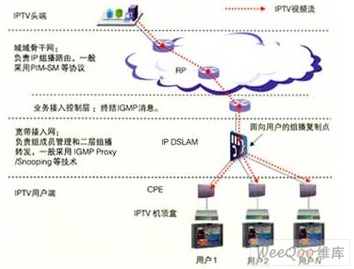
Figure 1 IPTV end-to-end multicast push network model
This paper describes the key configuration technologies of IPTV end-to-end multicast push network from two different network levels: metro backbone network and broadband access network.
2. Multicast key configuration technology for metro backbone network
2.1 Multicast Routing Technology
The main difference between a multicast packet and a unicast packet is the destination address of the packet. The destination address of the multicast packet is the multicast group address (the class D IP address starting with "1110"), and the unicast packet is the destination host IP address. The address is the destination address. Because there is no one-to-one correspondence between the multicast group address and the destination host, the multicast router can only use the uniqueness of the source address of the packet to perform routing decisions. That is, the multicast router sends the packet in the direction away from the multicast source according to the source address of the packet instead of the destination address. This technique is called reverse path forwarding (RPF).
To avoid routing loops, the RPF specifies that multicast packets must be forwarded from the specified upstream neighboring node to the local router. The multicast packets forwarded by other neighboring nodes are discarded. When a multicast routing problem occurs, multicast packets may not reach other paths as unicast packets. The IPTV live broadcast signal is interrupted on the backbone network, but unicast applications such as web browsing and mail sending and receiving are normal obstacles. At this time, the multicast router's RPF routing table and its upstream neighbor nodes should be checked along the multicast distribution path.
2.2 Multicast Routing Switching Technology
The multicast distribution tree in the PIM-SM protocol can be divided into two categories: source tree and shared tree. The source tree uses the multicast source as the root, which is also called the shortest path tree, to minimize the end-to-end multicast delay. However, the router must save a large amount of routing information and consume large system resources. The shared tree is RP (PIM-SM). The important routers in the protocol are used to route the multicast source to the multicast router. As the common root node of all multicast distribution trees, the multicast source traffic must be sent to the RP and then sent. The multicast path is usually not optimal. Additional network latency is introduced, but the routing information that the router needs to keep can be small.
The PIM-SM protocol leverages the advantages of both multicast distribution trees. In the initial stage of multicast, the multicast router cannot use the source tree because it cannot know the location of the multicast source. However, the known RP node and its shared tree can obtain the first few multicast packets sent by the multicast source. Know the location of the multicast source and switch from the shared tree to the source tree to reduce network latency and avoid network bottlenecks that may be caused by RP nodes.
The metro backbone network is generally composed mainly of Cisco routers. The routers such as Cisco implement the switching of the multicast distribution tree by using the traffic rate preset threshold SPT-Threshold. When the multicast flow rate of a multicast source exceeds the SPT-Threshold, the multicast route will be switched from the shared tree to the source tree. Similarly, if the multicast flow rate is lower than the SPT-Threshold, the multicast route will be multicast. You can also switch back to the shared tree from the source tree. The SPT-Threshold is configured to be 0. After the router receives the first multicast packet, it switches from the shared tree to the source.
2.3 RP Configuration Technology
As the root node of the shared tree, the RP plays a role in the multicast process. Considering that the PIM-SM protocol has the feature of switching the multicast distribution tree, the RP is generally used to establish the initial connection between the multicast source and the multicast router. Once the multicast route of the router is switched from the shared tree to the source tree, Then you need the RP and its shared tree. Therefore, the location selection of the RP in the multicast network is not very important, the key is its reliability and stability.
To improve the reliability and stability of the RP, you can select multiple multicast routers to share the RP function (that is, the Anycast RP technology), and configure the loopback interfaces of the RP nodes to be the same IP address. Fault protection.
The RP configuration problem in the multicast network is not only related to the deployment of the RP node itself, but also how other multicast routers know the problem of the RP node. In the initial stage of multicast, the multicast router may not know the multicast source location, but must know the RP address. There are two main ways for a multicast router to obtain an RP address, namely static configuration RP and automatic discovery RP. The static configuration of the RP is safe. It can effectively prevent spoofing behaviors such as RPs. However, the network configuration has a large workload and is not conducive to dynamic adjustment of nodes such as RP. The automatic discovery of RP can reduce the configuration workload and facilitate network change and control policies. Adjustment, but there are certain security risks. For a small-scale metro backbone network, you can configure the RP statically on each multicast router. For a metropolitan backbone network with a large-scale security policy, it is recommended to use the automatic RP.
2.4 IPTV headend multicast join technology
In the initial stage of multicast, the multicast router generally obtains the traffic and location information of the IPTV head end (ie, the multicast source) through the known RP node and its shared tree. To enable the RP to learn the multicast source, the multicast router directly connected to the multicast source is responsible for encapsulating the first multicast packets sent by the multicast source in an independent PIM Register message. Source registration process. The RP can obtain not only the multicast group packets of interest but also the IP address of the multicast source. After that, the RP forwards the multicast source information to other multicast routers, and ends the multicast source registration process through the PIM Registe-Stop message.
3. Multicast key configuration technology for broadband access networks
3.1 Multicast Join Technology for IPTV Clients
The IPTV client (set top box) performs signaling interaction with the multicast router of the metro backbone service access control layer (usually undertaken by the service router or the broadband access server) via the broadband access network through the IGMP protocol to join or quit the specific Multicast group (ie IPTV live channel).
When the set-top box sends a multicast group join request packet to the multicast router, the destination MAC address of the packet is the multicast group rather than the MAC address of the multicast router. This is different from the unicast mode. It should be noted that a multicast group MAC address actually corresponds to 32 different multicast group IP addresses. This is because the multicast group MAC address is 01:00:5E:00:00:00 to 01:00:5E:7F:FF:FF, that is, the effective address space is only 23 bits, and the effective address of the multicast group IP. There are 28 spaces in the space. The mapping between the two is equivalent to the lower 23 bits of the MACC address to the lower 23 bits of the IP address, resulting in the loss of the upper 5 bits of the IP address of the multicast group. For example, if two different IPTV live channels use 224.0.0.1, 224.128.0.1, and 239.128.0.1 as multicast group IP addresses respectively, the corresponding multicast group MAC addresses are 01:00:5E:00: 00:01, which will cause the Layer 2 devices of the set-top box and the broadband access network to distinguish the three signals. Therefore, you should pay attention to such problems when planning multicast IP addresses.
3.2 Layer 2 Multicast Forwarding Technology
The broadband access network consists of a large number of Layer 2 switches, DSLAMs, and other network element devices running at the data link layer. Layer 2 devices are characterized by exchanging/forwarding data frames based on MAC addresses between device ports. IP packet parsing and routing functions on Layer 3 (network layer) are poor. Therefore, IGMP cannot be directly supported. And other multicast protocols. When a Layer 2 device such as a switch handles IPTV multicast traffic, it broadcasts multicast data frames to all its ports according to the unknown destination address or broadcast mode. This is easy to cause broadcast storms.
To solve the problem of flooding multicast packets, you need to use Layer 2 multicast forwarding technologies, such as IGMP Snooping and IGMP Proxy. The IGMP snooping technology intercepts the IGMP messages between the set-top box and the multicast router by intercepting the IGMP messages between the set-top box and the multicast router. The IGMP proxy technology intercepts the IGMP messages between the set-top box and the multicast router. Filtering and proxy forwarding can save multicast traffic from the multicast router to the Layer 2 device. However, the requirements for processing power and memory of the NE device are high. When you configure a Layer 2 device, you can choose the actual performance of the NE device and the IGMP Snooping/Proxy technology.
The IPTV live channel with a bandwidth of 2 Mbit/s is used as an example. If the Layer 2 device does not use the Layer 2 multicast forwarding technology, the multicast packets sent to all IPTV users will be forwarded to all ports even if the user port has 10 Mbit/ s access bandwidth, the multicast packets of the five IPTV live channels can be blocked; after the Layer 2 multicast forwarding technology, the multicast packets are forwarded only to the port with the request, if each port is only down to the maximum. An IPTV set-top box forwards multicast packets (that is, 2 Mbit/s traffic) of at most one live channel to the corresponding port.
3.3 VLAN Configuration Technology
The traffic of Layer 2 multicast forwarding only involves IPTV multicast services and does not involve other broadband services. Therefore, in the broadband access network, technologies such as VLANs are generally used to isolate IPTV multicast traffic from traffic of other services and users. The commonly used VLAN technologies include the inter-VLAN multicast replication technology that solves the multicast VLAN to each user VLAN, and the QinQ technology that solves the problem that the number of VLAN IDs is insufficient.
3.4 Static Multicast and Dynamic Multicast Technology
The IPTV live broadcast program is delivered to the user terminal through the IP bearer network. There are two main multicast modes, namely dynamic multicast mode and static multicast mode. In dynamic multicast mode, a device such as a switch or a DSLAM receives and delivers the channel program only after receiving the first user join request from a certain channel (multicast group); and when the channel (multicast group) is last When a user logs out, the network element device stops receiving the multicast stream. In the static multicast mode, the MAC multicast forwarding entries of each IPTV channel (multicast group) are statically configured on the switching device. The multicast stream is delivered to the NE device regardless of whether the connected user is watching.
Static multicast traffic is independent of the number of IPTV users. It is only related to the number of channels and the bandwidth per channel. When the number of users is smaller than the number of channels, the traffic will be larger than the unicast traffic. The maximum number of concurrent multicast traffic is less than the number of channels. The time is equivalent to unicast traffic, which is equivalent to static multicast traffic when the number of IPTV concurrent users is greater than the number of channels. In static multicast mode, the user's channel switching speed is fast and the service perception is good, but the bandwidth requirement of the network is large. Dynamic multicast can minimize network traffic under any circumstances, but when the user receives a new channel. (Multicast group) may have a certain network delay.
When the number of IPTV users connected to the network device is very small, the advantage of multicast is not obvious. Therefore, in the initial stage of IPTV service development, when there are not many IPTV users or the broadband access network transformation is not in place, there is a traffic bottleneck. The IPTV live broadcast signal can be transmitted in dynamic multicast or even unicast mode. When the number of users connected to the network device far exceeds the number of IPTV channels, the bandwidth saving feature of multicast to network traffic becomes more and more significant. At this time, that is, when the IPTV service is in its mature stage and the broadband access network transformation is in place, the IPTV live broadcast signal can be transmitted in a static multicast manner to further improve the IPTV service quality. Therefore, the operator can determine whether the access network device is configured to be dynamic or static multicast according to actual conditions such as network quality and IPTV service penetration rate.
4 Conclusion
This paper combines the existing IP metropolitan area network of telecom operators to systematically expound the key technologies of IPTV end-to-end multicast push network configuration, which has good reference for telecom operators to deploy and implement IPTV services efficiently and economically.
Customized Solar Panel, 100watt solar panel,200watt solar panel, big solar panel, high efficiency high quality solar modules
different power customized and OEM logo customized solar panel
Customized solar panel data
solar cell type
mono crystalline half cut cell
power range
50watt to max 700watt
size and weight
different size and different weight if the power is different
solar panel type
monofacial or bifacial
solar panel color
sliver or black
Product details and pic


Customized Solar Panel,Noncrystalline Solar Panel Module,Cheap Price Pv Solar Module,Solar Photovoltaic Pv Panel
PLIER(Suzhou) Photovoltaic Technology Co., Ltd. , https://www.pliersolar.com