Speaker selection
The speakers described in this article all use anti-magnetic speakers. The tweeter uses the Yindi brand YDQG4-12 tweeter produced by Shanghai Leading Audio Instrument Co., Ltd., which adopts a series of Hi-Fi units such as imported silk diaphragm, magnetic liquid cooling system and fully enclosed antimagnetic magnetic circuit. The technology makes it more power-hungry than the common low-priced tweeters, and the sound quality is more delicate and feminine. The woofer uses the South Whale brand 4-inch spray cone anti-magnetic woofer produced by Nanjing Electro-acoustic Co., Ltd., model 110-8SX01. The technical specifications of each speaker are shown in Table 1. 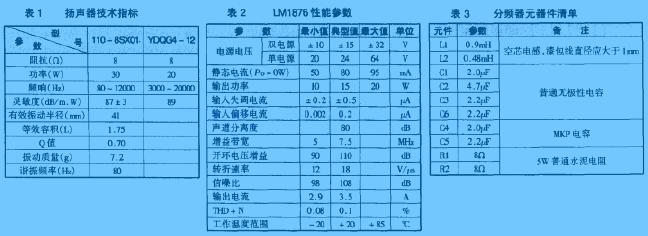
The height, width and depth of the speaker are 280mm × 120mm × 170mm (the internal effective volume is about 3.4L). The sheet is a medium density board with a thickness of 15 mm. The front panel dimensions of the left and right channel speakers are shown in Figure 1. Due to the small size of the speakers, the connection of the panels can be done with ordinary wood screws. 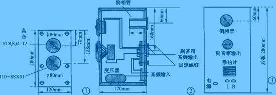
The inverted phase hole is located above the back of the box and has a length of 68mm. The author cuts off a 68mm long section from a PVC engineering plastic tube with a diameter of 60mm. Since the phase-inverting tube is on the back of the speaker, the rear panel of the speaker should not be placed close to the wall when placed, and should be more than 15cm away from the large-area reflecting surface such as the wall. Another thing to note is that behind the tweeter unit inside the cabinet, use a sound absorbing material (sponge) to make a shield (to surround the rear of the tweeter) to reduce the impact of sound waves from the woofer on the treble. Interference, making the treble brighter.
The power amplifier circuit is installed in the right channel speaker, so the rear panel layout of the left and right speakers is quite different. The length of the inverted tube and the side view of the main speaker are shown in Figure 2. The rear view of the main speaker is shown in Figure 3.
One of the two speakers is equipped with a power amplifier circuit as the main speaker and the other as a sub-speaker. Since the main transformer needs to be installed with a power transformer, it takes up a part of the space. In order to ensure the uniform internal volume of the two speakers, a wooden block with a similar volume to the power transformer can be attached to the bottom of the sub-speaker for balance. The decoration on the outside of the cabinet is free to choose according to personal preference.
This article refers to the address: http://
Power amplifier circuit
This multimedia active speaker has a small power, and it is enough to use a power amplifier with an output power of about 20W. In order to simplify the circuit, the power amplifier circuit in this speaker uses an integrated circuit, and the specific circuit is shown in Figure 4. 
Since the ordinary multimedia speaker does not have a headphone output jack, when the earphone is needed, the plug in the sound card output socket is repeatedly inserted and removed, which brings a lot of inconvenience. In this regard, the author designs a headphone jack in this speaker. When the earphone is not inserted into the socket, the internal contact of the socket is closed, and the audio signal output by the sound card is directly sent to the power amplifier circuit. When the earphone is inserted, the internal contact of the socket is disconnected, the sound card is cut off to the wiring of the power amplifier, and the audio signal output by the sound card is directly sent to the earphone, and there is no sound output in the speaker.
IC1 and surrounding components form a buffer amplifier stage, and the circuit gain = R4 / (R1 + R2) = 50 / (10 + 0.1) ≈ 5 times. In order to prevent the preamplifier input from floating when the sound card stops working after the computer is turned off, it is in the high impedance input state, and the sensed 50Hz AC signal is sent to the subsequent stage circuit for amplification, so that strong noise appears in the speaker. 22kΩ resistors R25 and R26 are specially set, which not only limits the input impedance to 22kΩ, but also prevents the front circuit from operating in a high-impedance state. It can also effectively suppress the 50Hz sensing signal and improve the signal-to-noise ratio of the whole machine.
The power amplifier integrated circuit uses the two-channel 20W high-fidelity power amplifier LM1876 produced by NS. The LM1876 is available in a 15-pin TO-220 package with squelch and standby modes. The main electrical parameters are shown in Table 2.
The LM1876 has a wide load range and can operate stably in the range of 4 to 30 Ω. The corresponding relationship between output power and load is shown in Figure 5. The supply voltage range of the LM1876 is ±10 to ±25V. When the supply voltage is reduced, the output power is only affected, but has little effect on other indicators. The corresponding relationship between the supply voltage and the output power is shown in Figure 6. The 6 and 11 feet of the LM1876 are left/right channel squelch control terminals. When these feet are connected to a high level (above 1.6V), the internal circuit of the LM1876 performs a mute operation to cut off the audio signal at the output end (as shown in Figure 7). Show). Therefore, an RC delay network can be connected between the positive voltage and the positive voltage, so that the output circuit has no audio signal output, and the output is delayed after a period of time, so as to avoid the startup moment. The output potential is detuned to the impact of the speaker. In FIG. 4, the transistors VT1, R24, C16, R20, and C15 are the startup delay networks, and the range of their values ​​can be adjusted to change the length of the delay time, thereby obtaining a satisfactory startup delay time. 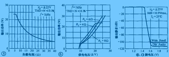
On the one hand, R11 and R16 in the circuit of Fig. 4 are the input terminal resistance of the power amplifier circuit, which determines the input impedance of the power amplifier circuit. For example, the resistors of R11 and R16 are 22kΩ, and the input impedance is 22kΩ. On the other hand, a bias current is supplied to the first stage differential amplifying circuit in the integrated block to make it work normally. It should be noted that the values ​​of R11 and R16 should not be too high, otherwise the midpoint potential of the output terminal will be high; but it should not be too low, otherwise the input impedance is too low, increasing the power consumption of the previous stage circuit and making the circuit output gain. decline. Their range should be between 15 and 51 kΩ.
R12 and R14 form a voltage divider and are connected to the integrated blocks 3 and 7 to form a negative feedback network. The amplification factor of this circuit is also determined by them. Magnification = (R12 + R14) ÷ R14 = (15K + 1.2k) ÷ 1.2k = 13.5. Therefore, as long as the resistance of R12, R14 is changed, the amplification factor of the circuit can be adjusted, but it should be noted that the magnification should be more than 10 times, otherwise the LM1876 will be unstable.
R15 and C7 form a speaker compensation network (or called a Jubel network) that absorbs the back EMF of the speaker and prevents circuit oscillations.
C8 and C9 are power supply bypass capacitors (ByPass bypass capacitors), which reduce the high-frequency internal resistance of the power supply and prevent the high-frequency self-excitation of the circuit, making the LM1876 work more stable.
The resistors in Figure 4 are all 1/4W five-color ring metal film resistors. The capacitors are WIMA metallized polypropylene capacitors except C15 and C16. NE5532 selects the products of American Big S Company (the products of Philips Company are also available, the unit price is about 10 yuan, and many 2-3 yuan on the market are not recommended). The volume potentiometer selects the ALPS product with low price and high quality. If the volume adjustment is troublesome, the volume potentiometer can be omitted, and it is connected with two 20kΩ resistors in series (the 8th and 13th pins of LM1876 are connected separately). The midpoint of the two resistors). In this way, the volume adjustment of the speaker can be adjusted by the “volume control†in the Wndows operating system (double-click or click the small speaker icon in the lower right corner of the display to adjust).
The power transformer uses a black and white TV power transformer with an output voltage of 16.5V×2. The power supply circuit is shown in Figure 8. 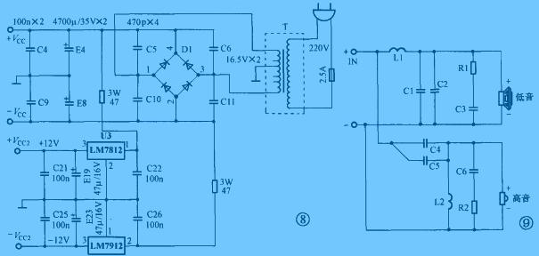
Divider circuit
Figure 9 is a circuit diagram of the speaker divider, with the crossover selected at 3 kHz. Since the speaker is an inductive load, when the signal frequency is different, its impedance changes greatly. Therefore, an impedance correction network composed of R1, C3, R2, and C6 is added to the frequency divider to approximate the load impedance of the frequency divider. Is a constant value. The parameters of the components used in the frequency divider are shown in Table 3.
Since the power amplifier block LM1876 generates a lot of heat during operation, it needs to be equipped with a heat sink. The author uses the scraped CPU heat sink to drill two small holes with the electric drill as the heat sink of the power amplifier circuit. When assembling, manually cut a rectangular hole similar to the heat sink area on the back panel of the main speaker, insert the inner wall of the heat sink into the hole, seal it with sealant, and then fix the LM1876 to the heat sink with bolts. Just above (the board should be insulated from the heat sink). The transformer is installed at the bottom of the main speaker (take the right channel as an example), and the power amplifier circuit can be installed in a suitable place in the speaker. The sound-absorbing cotton filled inside the main speaker cannot be in contact with the heat sink in the power amplifier circuit.
Wall Mount All In One Pc with the monitor and computer in the same metal case, which can attach to a wall by a VESA mount.
The back wall with holes for connecting machine , the standard of wall Mounting bracket is VESA 100*100 mm(length * width) for small size, and 200*200 or 300×300 mm for big one .
Wall screw specifications is M8.
Wall Mount All In One Pc
Wall Mount All In One Pc,All In 1 Computer,Wall Mountable All In One Pc,Allinone Computer
Guangzhou TouchWo Electronics Co.,Ltd. , http://www.touchaio.com