At present, domestic and foreign scholars have proposed a lot of lane line detection algorithms, which are mainly divided into two categories: one is based on image feature detection method, that is, feature-driven method, which is based on some features of road image (such as lane line color, width and Features such as edges) mark all points of the image as lane line points and non-lane line points. This mechanism requires that the lane line color of the road is more obvious and the edges are clearer, otherwise accurate detection results cannot be obtained; another method is based on The detection method of the model is to match the pre-defined lane line model according to the extracted features, and convert the lane line extraction into the calculation problem of the parameters in the lane line model. The assumptions of the model are mainly linear and curved models. The advantage is that it is not sensitive to noise and can better deal with the occlusion and coverage of objects in the image. This paper combines the texture features of the road and builds a model for lane detection, which not only makes full use of the information of the image, but also guarantees the robustness of the algorithm to some extent.
This article refers to the address: http://
In this paper, the image is preprocessed first, then Hough transform or Gabor transform is performed on the image to obtain the lane line position information, to determine whether the vehicle is driving in the lane, and if not, an early warning signal is issued.
1 image preprocessing
The preprocessing of the image is mainly to pre-process the image captured by the camera in real time, mainly including removing various noises of the image, and extracting the region of interest (ROI) of the image according to some parameters in the camera position adjustment algorithm, and performing edge detection. Etc., the purpose is to enhance the useful information of the image and suppress interference.
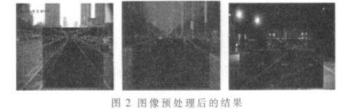
After calibrating the camera, select a certain area as the lane line detection area, perform smooth denoising, and detect the edge. This article uses Canny edge detection. Figure 1 shows the original road image taken, and Figure 2 shows the test results in different environments (day, cloudy, night).

2 Lane line detection based on Hough transform
2.1 Traditional Hough Transform Principle
For the case where the established lane line model is a straight line, the Hough transform is widely used as a method of lane line detection in the field of lane line recognition. The essence of the Hough transform is to coordinate the transformation of the image, making the result of the transformation easier to identify and detect. The expression of the Hough transform is:
Where (x,y) represents a point in the image space, Ï is the distance from the line in the image space to the origin of the coordinate, and θ is the angle between the line and the x-axis. The selection range of the traditional Hough transform voting space Ï and θ is usually Ï∈(0,r) (where r is the diagonal length of the image), θ∈(0,180). (Ï ,θ) is the parameter space after the coordinate transformation One point, which converts the point of the image space (xy) to the parameter space (Ï-θ), it can be proved that the point on the same line in the image space intersects the corresponding sinusoid in the parameter space (Ï , θ). Therefore, the coordinate transformation of the target point of the image space is projected into the parameter space, and the line equation corresponding to the image space can be found by counting the points with a large total number of votes in the parameter space.
As a classic lane detection algorithm, Hough transform has strong adaptability. However, this algorithm is time consuming. When the environmental factors outside the lane are not clear, or affected by some other factors on the road, the result is affected. The interference is large. The Hough transform test results are shown in Figure 3.

2.2 Lane line detection based on Hough transform improved by ROI region
In view of the fact that the lane lines of roads in the image are generally distributed on the left and right sides of the road, the application of the traditional Hough transform is improved, and the range of voting space is limited, that is, Ï and θ are defined to adjust the range of voting space. The polar angle and the polar diameter of the left and right lane lines are limited, and the camera is adjusted. Through continuous testing, the polar angle constraint area and the polar diameter constraint area of ​​the target point are obtained, and the region of interest (ROI) is obtained, as shown in FIG. Only the lane lines that fall within the white area are detected.
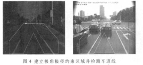
By establishing the polar angle and the polar diameter constraint area, a large number of interference points can be effectively removed, the interference of the adjacent lanes and the roadside tree buildings can be filtered out, and the running speed of the algorithm can be greatly improved. When the polar angle of the lane line is within the detection area, the position of the lane line can be quickly and accurately detected; however, when the image is shifted in the turn, lane change or camera position, the lane line easily exceeds the detection area, so that the result appears Great deviation.
3 Lane line detection based on Gabor filter
In view of the unclear road lane line and some other sign interference, this paper proposes an improved lane line detection algorithm, namely lane line detection based on Gabor filter. The vanishing point of the image is found by Gabor, that is, the intersection position of the two lane lines in the image, and then the Hough transform is performed on the vanishing point, which not only improves the applicability of the algorithm, but also improves the real-time performance of the algorithm.
3.1 Gabor transformation principle
The Gabor filter is similar to the biological function of the human eye, so it is often used for texture recognition and has achieved good results. The Gabor filter is a bandpass filter whose unit impulse response function (Gabor function) is the product of a Gaussian function and a complex exponential function. It is a function that achieves the lower bound of the time-frequency measurement uncertainty relationship, and has the best ability to balance the resolution of the signal in the time-frequency domain. The locality of the Gaussian function makes the Gabor filter only work locally, that is, it has good scale characteristics and directional characteristics. Therefore, Gabor filters are widely used in the fields of image processing and image analysis.
In this paper, some texture features such as the rutting mark and the edge of the lane line are analyzed to extract the vanishing point of the road and the information of the lane line.
The template calculation equation of the Gabor filter is as shown in the formula (2), and the template is divided into two parts: a real part (formula (3)) and an imaginary part (formula (4)).
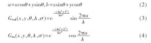
By creating a K×K size Gabor template, (x, y) represents a point in the image space. Where θ represents the direction of the template, in order to determine the final road texture direction, the selection range is 0~72; λ represents the wavelength of the road surface; σ represents the noise capacity, and σ=K/9 is taken in this paper.
3.2 Solution of vanishing point
In this paper, the template is convolved with images in different directions. For any point of the image, the result of convolution in a certain direction is the maximum value. This maximum value is the energy corresponding to the texture direction, and the direction is the direction of the texture.

Where α denotes the direction corresponding to the template, and any point I(x, y) in the image is convolved with the Gabor template in the α direction to obtain different t(x, y), and the maximum value is obtained, and the maximum value is obtained. The corresponding direction is taken as the texture direction of the (x, y) point in the image, and the maximum value is taken as the texture intensity in the texture direction.
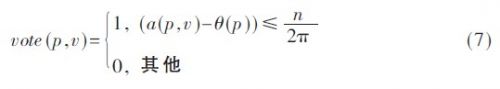
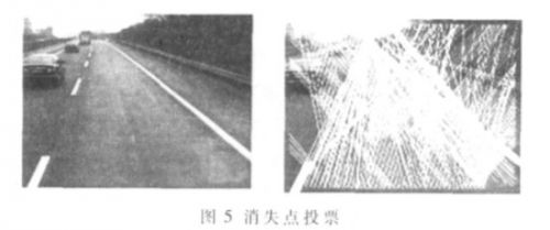
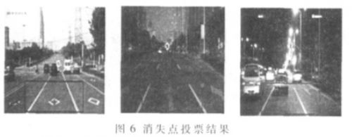
The texture direction and energy of each point in the image can be obtained by calculation. To calculate the vanishing point, vote for the selected point in the image, here select a certain area point below the image, as shown in Figure 5. When the texture energy is greater than the set threshold, the point is the voting point, p is the point of the voting space in the image, θ (p) is the p texture direction, v is the candidate point of the vanishing point, and a (p , v) is the p point and v. The angle of the point, n is the number of Gabor template directions used, R is the defined voting space, that is, the box area corresponding to Figure 6, and the voting result of p point to v point is counted by vote (p, v). Votes (v ) is the statistical result of voting for the accumulation of the R region, and pvote is the coordinate of the point where the number of votes is the highest, that is, the vanishing point.
The box in Figure 6 indicates the selected voting area, that is, 400 points are selected in the area for Gabor transformation to find the texture square and energy; the circle is the found vanishing point position.
3.3 lane detection
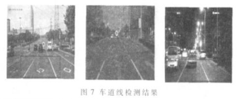
For the traditional Hough transform, it is necessary to traverse each angle of each point, which is time consuming. In this paper, the improved Hough transform is used to perform Hough transform on the vanishing point and the surrounding pixels. The two peak points of the left and right lane lines are obtained, and the lane lines are drawn. The method can effectively suppress other edge noise interference of the image and improve the real-time performance of the algorithm. The lane test results are shown in Figure 7.
3.4 lane line tracking
Tracking is divided into vanishing point tracking and lane line tracking.
(1) Tracking of vanishing point: The vanishing point is generally far away. The range of the vanishing point of the vehicle during the running is not very large, and the road near the lane line is more frequent due to the contact of the vehicle tires, the texture is more obvious, and the contribution to the vanishing point Larger. Therefore, randomly select 100 points on both sides of the lane line to vote for the vanishing point and several points around it (36 points are selected in this paper), as shown in Figure 8.
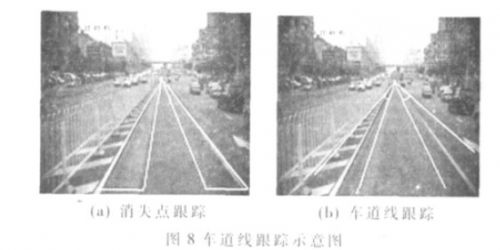
(2) Lane line tracking: According to the result of the previous frame measurement, the limited angle is within a certain range of variation (this article is limited to the range of 10°, as shown in Figure 8(b)), and the Hough transform is performed, which greatly reduces the operation speed. The program is reinitialized when the vanishing point of the image detection and the point on the lane line are less than the set threshold.
4 lane recognition
Based on the application, this paper calculates the BRT lanes of Hefei and Shenyang. The BRT lanes have the following characteristics compared to other lanes: the left and right lane lines are yellow, generally located on both sides of the road, with railings or road teeth on both sides of the road. feature. Based on this feature, this paper implements the BRT lane recognition system, combined with GPS to determine whether there is a BRT lane in its location range, and if so, whether the lane line color is yellow, that is, establish a color model, and each color on the lane line Mark it and comprehensively judge whether the left and right lane lines are yellow lane lines, and mark the yellow, as shown in the left figure of Figure 9. Because the lane line is subject to wear and tear for a long time, and it is difficult to accurately identify the color under the illumination of the yellow light at night, this paper combines the features of the railings and road teeth to identify the lane, and the certain areas on both sides of the detected lane line (Figure 9 right white) The rectangular area is compared to compare the feature differences such as the color edge texture. Through a large number of tests, this paper obtains a priori threshold to determine whether it is a BRT lane. When the rectangular area difference is greater than the set threshold, it is judged as a bus lane, thus accurately implementing lane detection.

5 Experimental results and analysis
The specific process for implementing BRT lane recognition is shown in Figure 10.
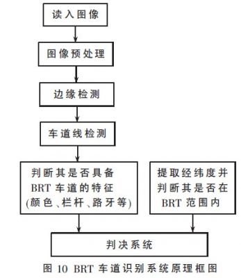
This paper first collects the latitude and longitude information of the area where the vehicle is located by GPS, and establishes the road latitude and longitude information base to determine whether there is a BRT dedicated lane near the location of the vehicle. If there is, then the lane line detection is performed, the left and right lane lines of the lane where the vehicle is located are found, and the lane is judged. The online color information and the brightness of the edge of the lane line are analyzed to determine whether it has the characteristics of the BRT express bus lane. If it is available, it can be used as a basis for monitoring whether the vehicle in front is illegally entering the BRT lane.
6 Improve the application
The model is not only applicable to structured roads with lane lines such as roads, but also to unstructured roads such as rural dirt roads with clear ruts and tarmac roads without lane lines, which can accurately detect the vanishing point of roads. When the vehicle's traveling direction deviates from its vanishing point, the driver is reminded to take corresponding measures, thereby realizing the lane departure warning, which can effectively suppress the occurrence of the accident. Figure 12 shows the Gabor convolution operation on the white area, and draws the direction of the point where the convolution result is large (that is, the energy is large), as shown in the right figure of Figure 12. It can be seen that the direction basically points to the vanishing point of the road. Figure 13 shows the vanishing point of a complex road, where the circle represents the vanishing point voting result.
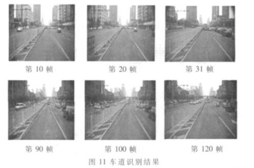

In this paper, a lot of experiments are carried out on the Hefei bus lane. The experimental results show that the algorithm has strong applicability, can accurately detect the lane line of the lane where the vehicle is located, and make a correct judgment on the lane. The lane recognition result is shown in Figure 11.
This paper proposes a lane detection method based on road texture features, and successfully transplants the linear model algorithm to the DM6437 development platform. The road image is collected in real time by the camera (25 S/s, image size is 720×576), the lane line information is calculated in real time, and a large number of experimental tests are performed on the urban road. The average algorithm time per frame is controlled at 50 ms. Within the range, the position of the lane line can be detected more accurately, and has strong real-time and robustness.
Gear Wall Clock,Gear Clock Wall,Wall Clock Exposed Gears,Stainless Steel Gear Wall Clock
Guangzhou Huanyu Clocking Technologies Co., Ltd. , https://www.findclock.com