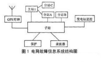
The intelligent fault information system (hereinafter referred to as the system) is responsible for the collection and analysis of fault information during grid faults, providing accurate fault diagnosis for the operation dispatcher to facilitate rapid fault handling and reduce losses caused by faults. As shown in Figure 1, the system can be divided into three layers of the main station, sub-station and sub-station. The substation is installed in the substation and is responsible for data acquisition and preprocessing tasks.
Based on the analysis of the new requirements of the smart grid to the fault information system substation (hereinafter referred to as the substation), this paper proposes a hardware platform based on the CPCI bus embedded device as a substation, which is easy to expand. With strong features and good compatibility, it can meet the hardware requirements of the new generation of substations.
1 Current status and requirements of substation hardwareThe proposed smart grid puts higher demands on the substation. The goal of the smart grid is to rely on advanced computer control technology to accurately deliver power to users through transmission and distribution, improving energy efficiency and energy supply. The smart grid requires the dispatching system to have a rapid response capability to faults, obtain detailed details of the faults in a short period of time, and formulate corresponding control decisions. For this reason, the traditional manual processing methods cannot meet the requirements of the smart grid.
Smart grid technology improves the observation capability of the substation, and the amount of data that the sub-station needs to process when the fault occurs is significantly improved. At the same time, the progressive implementation of the smart grid makes the sub-station hardware compatible with the access of the traditional device, which requires the use of powerful Substation hardware that can be flexibly configured to complete fault information collection and intelligent pre-processing tasks at the substation level.
The digital substation is the basis for realizing the smart grid. The new-generation communication standard IEC61850 follows that the devices in the substation should meet the interoperability and finally realize the interchangeability of devices from different manufacturers. At present, the hardware devices in the substation are divided into two categories: one is the industrial computer (IPC), and the other is the device developed by each manufacturer. Both types of devices cannot fully meet the requirements of the smart grid for the substation hardware, which is reflected in the following aspects:
1) The industrial computer has the disadvantages of large power consumption, difficulty in expansion, and loss of rotating parts. Although most of the devices developed by the manufacturers use the bus technology and the plug-in form makes the device have certain expandability, the manufacturer's customized backplane bus and plug-in do not follow the same international standards, which limits the devices between the manufacturers. The versatility, the device can not be plug-in level interchangeable.
2) The different hardware in the substation has caused the complexity of substation project implementation. Due to the large difference in hardware principle and operation method, users must be familiar with the hardware configuration methods and performance indicators of different types of devices in different substation construction and maintenance processes, which increases the construction difficulty, improves the probability of error, and reduces the reliability.
3) Software and hardware association of self-developed devices in substations
The degree is high, which makes the separation of software and hardware difficult. Users can only purchase hardware from a few industry manufacturers, not only the procurement cost is high, but also the advanced technology equipment produced by non-industry manufacturers can not be purchased. The hardware upgrade is slow, and it cannot adapt to the ever-increasing amount of large data and high reliability in the era of smart grid. need.
4) In the process of power technology development, the situation of coexistence of new and old devices will exist for a long time, and the performance improvement of hardware and the development of new functions will continue. Due to the fixed hardware interface of the industrial computer and the manufacturer's custom device, the expansion capability is poor, so the overall replacement is often performed during the upgrade process, which increases the user cost and easily causes the device to be unstable.
2 CPCI technology introductionCompact PCI (Compact Peripheral Componen TInterconnect, CPCI) is a bus interface standard proposed by PCI Industrial Computer Manufacturer's Group (PICMG) in 1994. It is a high-performance industrial based on PCI electrical specifications. Use the bus. A CPCI system consists of one or more CPCI bus segments. Each bus segment is composed of eight CPCI slots (33 MHz case), each CPCI bus segment including one system slot and up to seven peripheral slots. Figure 2 shows a 33 MHz CPCI bus segment structure.
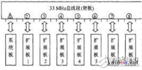
Figure 2 A CPCI bus segment structure
Compared with IPC, the CPCI system has obvious advantages:1) The CPCI system adopts the European card structure and has good heat dissipation performance and vibration and shock resistance. The ESD (Electro.StaTIc Discharge) electrostatic strip on the CPCI board meets the electromagnetic compatibility requirements. At the same time, the redundancy design, failover and fault management defined by the CPCI bus standard are in line with the scalability and high reliability requirements of the system in the IEC61850 standard, which is consistent with the modular concept of IEC61850.
2) The CPCI system replaces the gold finger with a pinhole connector. The CPCI card is fixed on the back plate through the connector. The top and bottom are supported by the guide rails. Even in the case of severe shock and vibration, the permanent connection can be ensured without contact. bad. Installing and replacing a CPCI board is very simple. In addition, the CPCI system pins are staggered to support hot swapping.
3) The CPCI system has sufficient bandwidth, such as PICMG 2. The x version provides up to 512 MB of bandwidth per second on a 64-bit/66 M-bus interface, while the PICMG 3.0 version has a bus speed of over 2 Tb per second.
3000 Puffs Vape,Breeze Vape Pod,Disposable Oil Vape Pen,Electronic Cigarette Aim Stick
Guangzhou Yunge Tianhong Electronic Technology Co., Ltd , https://www.e-cigaretteyfactory.com