Image dehazing system. A Retinex real-time image dehazing method based on ZYNQ is proposed. The Retinex algorithm is used to defogging the luminance component V in the HSV color space. The ARM+FPGA hardware and software cooperation method is used to complete the algorithm control function and the color space conversion of the image. Simple calculations such as logarithms, logarithmics, etc.; parallel light algorithms using Gaussian kernel functions and 2D image convolutions to estimate ambient light illuminance. Experimental results show that the proposed method has the advantages of fast processing speed, small size, embeddability, portability, low power consumption, etc., and can meet the performance requirements of outdoor video systems.
introduction
Because of hazy weather, the quality of the image obtained by the outdoor vision system will be seriously degraded, which will not only result in ambiguity, but will reduce the contrast, but will also cause serious color shifts and distortions, which will affect the stability and accuracy of outdoor vision systems. Therefore, it is extremely important to perform effective and quick dehazing processing on degraded images caused by hazy weather.
Common defogging methods fall into two categories: dehazing based on image restoration and dehazing based on image enhancement. The former is based on the cause of image degradation. A physical model of the defogged image is established, and a clear defogged image is recovered according to the model. The defogging effect of this method is good, but the complexity of the algorithm is large and it is not easy to implement on the hardware platform. The image-enhancement-based defogging method does not consider the causes and mechanisms of image fogging, but selectively enhances the required details. The commonly used dehazing method for this class is the Retinex algorithm [4]. Retinex algorithm can retain the details of the image such as the edge, the processed image has the advantages of moderate brightness, high contrast. The existing defogging algorithms are mostly implemented on PCs, and their portability and flexibility limit the application in outdoor video systems.
ZYNQ is a Xilinx-based all-programmable system on chip, which integrates a dual-core ARM Cortex-A9 and FPGA, and has a large number of logical units, digital signal processors (DSPs), and other resources. Meet the real-time processing, miniaturization, embeddability, portability, and low power consumption of outdoor video systems.
Based on this, this paper proposes a Retinex real-time image dehazing method based on ZYNQ and uses ZYNQ's ARM+FPGA software and hardware cooperation to improve the image dehazing performance of outdoor video systems. In order to reduce the algorithm complexity and color fidelity, the method performs Retinex defogging processing on the luminance component V in the HSV color space, linearly stretching the saturation S to expand the dynamic range, and keeping the hue H unchanged to avoid color distortion. In terms of implementation architecture, some simple calculations are performed by ARM, such as logarithm, subtraction, linear stretching, and color space conversion in the Retinex algorithm. However, the two-dimensional convolution of the Gaussian kernel function with the image is complicated and time-consuming. Calculations are passed to the FPGA using a parallel algorithm to increase the real-time processing speed. The data exchange between ARM and FPGA is carried by the on-chip bus AXI4 (Advanced eXtensible Interface 4) [5].
1
Traditional Retinex algorithm
The Retinex theory states that an image can be decomposed into incident and reflected components of the image, that is:
2
Algorithm optimization
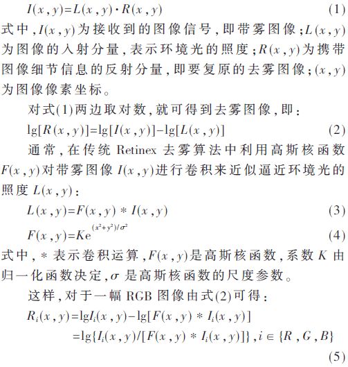
In the traditional Retinex algorithm, the three channels R, G, and B of the image are processed separately, which easily causes color distortion. Moreover, the amount of calculation is very large in the hardware implementation, and it is difficult to meet the real-time requirements of the system. Therefore, this paper uses Retinex algorithm based on HSV color space. The image with fog is converted from RGB color space to HSV color space, and the hue H, saturation S, and brightness V with less correlation are obtained, and the H component of the image is kept unchanged, and the saturation component S is linearly stretched. The V component is processed by the single-scale Retinex algorithm, which can not only reduce the computational complexity of the algorithm, but also avoid the defects that the traditional Retinex algorithm can easily cause color distortion. The algorithm flow chart is shown as in Fig. 1.
The specific implementation steps are as follows: Select the appropriate σ value and template size, construct the Gaussian kernel function according to equation (4); convert the fogged image from the RGB color space to the HSV color space; according to the Retinex algorithm, take the logarithm of the luminance component V V1; Substituting the component V into the convolution of the formula (3) with the Gaussian kernel function, and then taking the logarithm to obtain the ambient light illuminance estimated value V2; the V1 component and the V2 component are subtracted to obtain the luminance component V3 processed by the defogging algorithm; The saturation component S is stretched to obtain S1; the hue component H, the stretched saturation component S1, and the luminance component V3 processed by the Retinex algorithm are converted into an RGB color space and output to complete the image defogging process.
3
Hardware platform implementation
The hardware platform is based on the Zynq-7010 development board. The design of the image dehazing system is implemented using ARM+FPGA[6]. Image defogging system, image data as data input; logarithmic module, color space conversion module, subtractor, linear stretching S module and display control completed in ARM; a large amount of calculation, take a long time convolution operation Running in the FPGA.
3.1 Normalization of Image Data
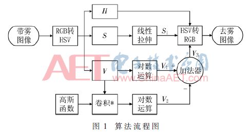
In order to increase the calculation speed and reduce the FPGA resource consumption, fixed point data is used in the design to save the data and perform calculations. Experiments show that for the range [0,1] of image data HSV, when the error is less than 4×10⁻³, no obvious loss of image detail information will occur. Therefore, with the value field [0,1] of the 0.003 906 normalized image data, the image data can be represented by an 8-bit binary fixed-point decimal as shown in Fig. 2. The decimal point is fixed to the left of the highest position, indicating the range is [0, 0.996 ], The minimum resolution is (0.00000001)2≈0.003 906.
3.2 ARM Part Algorithm 3.2.1 Logarithmic Module
The Retinex algorithm requires a logarithm operation of the fogged image I(x,y) and the incident component of the image (ambient light illumination) L(x,y). In the ZYNQ system, in order to reduce the quantization error and improve the real-time performance of the operation, a logarithmic lookup table method based on 2 is used here to implement the logarithm operation.
Since the image data I (x, y), L (x, y) has been normalized to the 8-bit binary fixed-point fraction shown in Figure 2, its range ∈ [0, 0.996], the minimum resolution is 0.003 906, There are 256 data values. The logarithm of 0 is -∞, which cannot be directly quantified. Therefore, [0,0.995] is divided into two parts: {0}∪[0.003 9,0.995]. [0.003 9,0.995] corresponds to the logarithmic domain ∈ [-8, -0.007]. When the error is less than 4×10⁻³, the logarithmic value can be 1 bit sign bit + 7 bit integer bit + 8 bit decimal place total 16 A signed binary fixed-point representation of bit; log20 is approximated by the maximum negative number -128 that can be represented by a 16-bit signed binary fixed-point number. Finally, the 256 16-bit logarithm values ​​after quantization are stored in the lookup table LUT[ ].
Let X denote the 8-bit binary fixed-point decimals where the image data I(x,y) and L(x,y) have been normalized, and use Y to represent the 16-bit signed binary fixed-point numbers of the logarithm operation results. The lookup table method can be expressed as:

The function int( ) represents the rounding of binary numbers.
3.2.2 Linear Stretching
During the defogging process, the saturation S is relatively decreased with the increase of the image brightness V. Therefore, in order to maintain the original vividness of the image color, it is also necessary to enhance the saturation S of the image. Here, the saturation S is stretched by three-stage linear stretching.
3.3 FPGA Partial Algorithms 3.3.1 Gaussian Kernel Function Normalization
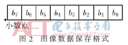
Experimental simulations show that when σ=40 and the filtering template is 101×101, the detineting effect of Retinex algorithm is better. At this time, the range of the Gaussian kernel function is [2.085×10-5,9.947×10-5], and the numerical value is small. If it is directly quantized, the number of data bits is wider, and it will increase the resource consumption. Since the convolution operation is a linear operation, the Gaussian kernel function can be expanded first, and then the convolution result can be reduced by the same multiple without affecting the final calculation result. Here, the Gaussian kernel function is expanded 27-fold, and the range of the Gaussian filter function after the expansion is [0.0027, 0.017]. The error is less than 2.56×10⁻⁴, and there is no obvious loss of detail information in the defogging image. Then use 2.44×10⁻⁴ normalization to enlarge the range of the Gaussian kernel function 27 times [0.002 7, 0.012 7], that is, use 1 bit sign bit + 3 bit integer bit + 12 bit decimal place total 16 bit binary fixed-point decimal As shown in Figure 3, the range is [-8,7], and the minimum resolution is (0.000000000001)2≈2.44×10⁻⁴, which can meet the accuracy requirements. Finally, the value of the Gaussian kernel function quantized into a fixed-point number is stored in the form of a row as an initialization file, and is directly solidified into a block random access memory (BRAM) of the FPGA in the form of ROM.
3.3.2 Convolution Module
The convolution operation consists of a large number of matrix multiplications and additions. Since the algorithm is a parallel structure, the convolution operation is designed to be implemented in the chip's FPGA. The overall framework structure of the algorithm is shown in Figure 4.
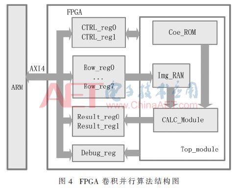
ARM sends picture data and control information to the FPGA control register CTRL_reg and image data register Row_reg through the AXI4 bus, and reads the current state of the control register and the result in the convolution register Result_reg through AXI4.
The top-level convolutional operation module consists of a Gaussian Kernel ROM block Coe_ROM, an image block RAM Img_RAM, and a calculation module CALC_Module 3. The Gaussian kernel function used in the convolution is stored in the BRAM of the FPGA and read in the ROM format. The image block RAM The size is the same as the size of the filtering kernel. The main control program reads Gaussian kernel functions and pixel data from Coe_ROM and Img_RAM respectively and sends them to the calculation module for calculation, and sends the result of the calculation to the result register Result_reg.
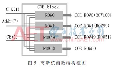
Since the Gaussian filtering kernel is 90° rotationally symmetric, and the Gaussian kernel function does not change in the program, in order to save storage space and reduce the complexity of the logic control, only the upper part of the Gaussian kernel function is stored in the program to form a Gaussian kernel. The function structure is shown in Figure 5.
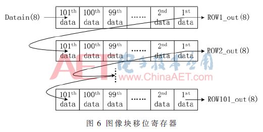
In order to increase the calculation speed, the block of image data RAM is saved using shift register, the block of image RAM slides from top to bottom and from left to right, and the convolved data is re-prepared at the top of each column, and then the convolution block is convoluted. Swipe down. Each time you calculate a point, swipe down one line. The shift register structure of the image block RAM is shown in Figure 6.
4
Experimental results and analysis
In the experiment, the hardware platform used the black gold development board ALINX7010 based on Zynq-7010. The FPGA clock was 250 MHz. The program was built using Xilinx Vivado 2016.3 and was simulated using its own simulation software.
4.1 Experimental results
To verify the performance of the proposed method, the proposed method was compared with the performance of the Retinex algorithm implemented in a PC (Core i5 6600K, 4.1 GHz, 16 GB RAM, MATLAB 2013a). Both methods choose σ=40 and the Gaussian template size is 101×101.
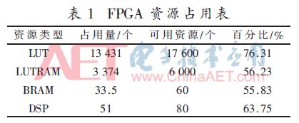
FPGA resource occupancy indicators include: LUT, look-up table RAM (LUTRAM), BRAM, DSP, and so on. Table 1 shows the four resource occupancy tables for the FPGA part of the ZYNQ hardware.
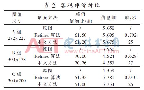
The peak signal-to-noise ratio, information entropy and running time were used as three objective technical indicators to evaluate the effects of image defogging. The peak signal-to-noise ratio is a ratio used to describe the maximum possible power of a signal and the destructive noise power that affects it. Information entropy is a technical index to measure the amount of information contained in an image and the richness of image details. The larger the entropy value is, the larger the amount of information contained in an image is, and the more detailed the image is[7].
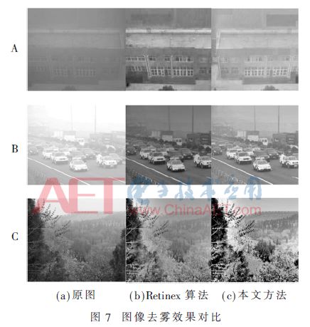
Figure 7 shows the comparison of the effects of the three groups of image defogging experiments. Table 2 shows the Retinex algorithm implemented in PC and the peak signal-to-noise ratio, information entropy, and running time of the three experimental examples mentioned above. Comparison of performance indicators.
4.2 Analysis of Results
From Table 1, we can see that the LUT occupies 76.31% of the FPGA resources, and the LUTRAM, BRAM, and DSP occupy about 50% of the FPGA resources, indicating that the entire system consumes less Zynq-7010 resources, which means that the required hardware costs are lower and can meet the requirements. The actual project needs.
From the images of group A, B and C in Fig. 7, it can be seen that both the Retinex algorithm implemented by PC and the image dehazing method presented in this paper have obvious defogging effects.
It can be seen from Table 2 that the peak signal-to-noise ratio of the two algorithms has reached more than 50 dB, which can effectively filter out the noise caused by fog in the image and improve the clarity of the image. The information entropy of the processed image is higher than that of the fogged image, indicating that the image detail information after defogging has been enhanced. Compared with the traditional Retinex dehazing algorithm on the PC, the proposed method achieves the same level of peak signal-to-noise ratio and information entropy, and the operating speed is increased by more than 28 times, reaching more than 25 frames per second. Real-time processing speed. The experimental results show that the image defogging is achieved on the ZYNQ platform. With the good defogging effect, it has the advantages of fast operation speed, high portability, and low power consumption, which can meet the practical requirements of outdoor video systems.
The material of this product is PC+ABS. All condition of our product is 100% brand new. OEM and ODM are avaliable of our products for your need. We also can produce the goods according to your specific requirement.
Our products built with input/output overvoltage protection, input/output overcurrent protection, over temperature protection, over power protection and short circuit protection. You can send more details of this product, so that we can offer best service to you!
Led Adapter,Mini Led Adapter,Security Led Adapter,Waterproof Led Adapter
Shenzhen Waweis Technology Co., Ltd. , https://www.huaweishiadapter.com