The design includes a battery polarity automatic identification circuit, which eliminates the need for manual polarity switching and makes the device more user-friendly. This feature ensures that regardless of how the battery is connected, the charging process will still work correctly without any user intervention.
First, the Circuit Principle
As shown in the schematic diagram, Q1 along with its surrounding components forms a self-oscillating circuit. After the transformer B steps down the voltage and D5 rectifies it, a DC voltage of 9.4 volts is generated on C4. The current is limited by R6. Then, Q10 (TL431) regulates the voltage, and a stable 4.23 volts is output from the emitter of Q3 to charge the lithium battery.
The polarity automatic identification circuit consists of Q5 to Q8 and resistors R12 to R15. When point A is connected to the positive terminal of the battery and point B to the negative terminal, Q8 turns on due to the positive bias voltage provided by R12, while Q5 is turned on via R14. This allows the charging current to flow through the path: Q5 → Point A → Battery E → Point B → Collector of Q8, thus completing the charging cycle.
If the polarity is reversed—point A connected to the negative terminal and point B to the positive—the charging current flows through Q7 → Point B → Battery E → Point A → Collector of Q6, forming an alternative charging path. This mechanism automatically detects and adapts to the battery's polarity, ensuring safe and effective charging.
When the charging current passes through R6, Q4 turns on, causing LED1 to flash. LED1 is a three-color LED with an internal oscillator, allowing it to randomly display different colors as it flashes. Once the battery is fully charged, Q4 turns off because there is insufficient conduction voltage, and LED1 stops flashing. LED2 serves as the power indicator, lighting up when the system is active.
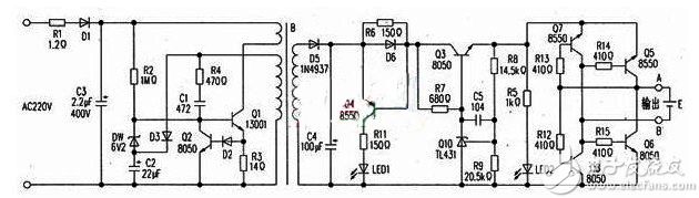
Circuit schematic
Second, Common Troubleshooting
Fault 1: The power indicator is off.
Diagnosis: The Q1 transistor was found to be functioning normally, but there was no bias voltage at the b terminal. Further testing revealed that R2 was open-circuited. Replacing R2 resolved the issue.
Fault 2: The power indicator is off.
Diagnosis: Testing showed that Q1 was damaged, and both R1 and R3 were open. All other components tested normal. After replacing these faulty parts, the system returned to full operation.
Cable Accessories,Performed Strain Clamp,Aluminium Alloy Preformed Guy Grip Dead End
Shahe Yipeng Import and Export trading Co., LTD , https://www.yppolelinehardware.com