The design features a battery polarity automatic identification circuit, eliminating the need for manual polarity switching and offering a more user-friendly experience. This system ensures that regardless of how the battery is connected, the charging process will still work correctly, making it ideal for users who may not be familiar with electronics.
First, the Circuit Principle
The circuit diagram is shown above. Q1, along with its surrounding components, forms a self-oscillating circuit. After the transformer B steps down the voltage and D5 rectifies it, a DC voltage of 9.4 volts is generated across C4. R6 limits the current, and then Q10 (TL431) regulates the voltage. The emitter of Q3 outputs a regulated 4.23 volts, which is used to charge the lithium battery.
The polarity auto-detection circuit consists of Q5 to Q8 and resistors R12 to R15. When point A is connected to the positive terminal of the battery and point B to the negative, Q8 turns on due to the positive bias from R12, while Q5 is turned on by R14. This creates a charging path through Q5 → A → Battery E → B → Q8’s collector. If the polarity is reversed—point A connected to the negative and B to the positive—the charging path switches to Q7 → B → Battery E → A → Q6’s collector, allowing the charging process to continue without manual adjustment.
When the charging current flows through R6, it triggers Q4 to turn on, causing LED1 (a three-color LED with an internal oscillator) to flash in different colors. Once the battery is fully charged, the voltage across R6 drops below the threshold, turning off Q4 and stopping the LED’s flashing. LED2 serves as a power indicator, lighting up when the device is powered on.
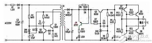
Circuit schematic
Second, Common Troubleshooting
Fault 1: The power indicator is off. Overhaul: Q1 was tested and found to be functioning normally, but there was no voltage at the b-terminal. Upon checking, R2 was found to be open. Replacing R2 resolved the issue.
Fault 2: The power indicator is off. Overhaul: Testing revealed that Q1 was damaged. Further inspection showed that R1 and R3 were also open. After replacing these components, the device returned to normal operation.
These troubleshooting steps highlight the importance of checking key components like resistors and transistors when diagnosing issues. By following this methodical approach, most common faults can be quickly identified and resolved, ensuring the circuit operates efficiently and reliably.
Fastener,Gain Grid For Utility Fastening,Hot Dipped Galvanized Bolt,High Quality Grid Steel Plate
Shahe Yipeng Import and Export trading Co., LTD , https://www.yppolelinehardware.com