Abstract: The design uses AT89C51 single-chip microcomputer, A/D converter ADC0808 and common anode digital tube as the main hardware. The design and programming method of digital voltmeter Proteus software simulation circuit are analyzed. The single-chip microcomputer is applied to the measurement technology, and the analog signal is converted into a digital signal by using ADC0808, and the data processing is realized by AT89C51, and the display is completed by scanning through the digital tube. The designed digital voltmeter can measure the voltage value of 0~5 V. The AT89C51 is an 8-bit single-chip microcomputer. When the input voltage of ADC0808 is 5 V, the output digital value is +4.99 V. The design circuit is simple, low in cost and stable in performance.
 
introduction
With the development of electronic science and technology, electronic measurement has become a means that must be mastered by the majority of electronic workers. The requirements for measurement accuracy and function are also getting higher and higher, and the measurement of voltage is very prominent, because voltage measurement is the most common. The digital voltmeter is a voltmeter designed with digital measurement technology. Compared with the analog voltmeter, the digital voltmeter has the characteristics of intuitive reading, accurate display range, high resolution, high input impedance, high integration, low power consumption, strong anti-interference ability and strong expandability. Wide range of applications in voltage measurement and voltage calibration. Proteus software is a circuit analysis and physical simulation software. It runs on the Windows operating system and can be used for simulation and analysis (SPICE) of various analog devices and integrated circuits. It is a simulation software that integrates single-chip microcomputer and SPICE analysis. It is powerful, with rich system resources, less hardware investment, and intuitive image. And other advantages, in recent years by the majority of users.
   1 system overview
   1.1 Design tasks
Use the single-chip AT89C51 and ADC0808 to design a digital voltmeter, convert the voltage value between 0~5 V of the analog signal into a digital signal, display it as a two-digit digital tube, and observe the voltage value of the ADC0808 analog input signal through the virtual voltmeter. The LED digital tube displays the corresponding numerical value in real time.
   1.2 overall plan
The block diagram of the digital voltmeter circuit is shown in Figure 1.
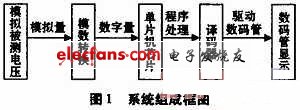
The circuits that need to be used in this design include a power supply circuit, an analog-to-digital conversion circuit, a single-chip control circuit, and a display circuit. The chips that need to be used in the design are AT89C51 MCU, ADC-0808, 74LS74, LED digital tube, etc.
   2 Digital voltmeter Proteus software simulation circuit design
The voltage input signal to be tested is A/D converted by the analog/digital conversion circuit within the maximum operating voltage range of the ADC0808 chip, and the program data is processed by the single chip control circuit, and then the digital tube is realized by the seven-segment decoding/driving display circuit. The input voltage is displayed.
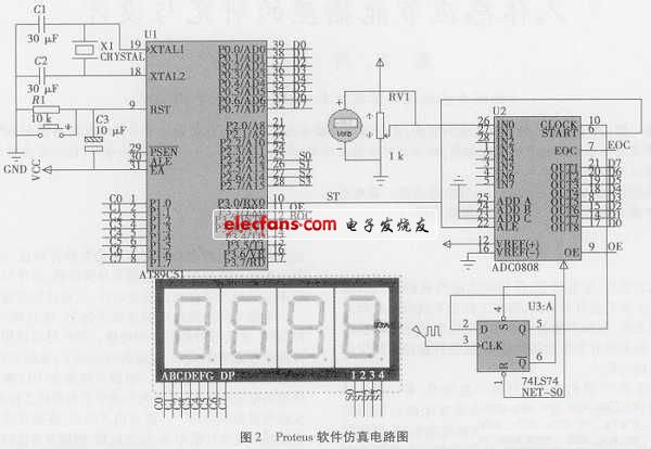
The hardware circuit schematic is shown in Figure 2.
   2.1 Interface design of AT89C51 single-chip microcomputer and digital tube display circuit
Using the single-chip AT89C51 and ADC0808 to design a digital voltmeter, the DC voltage value between 0~5 V of the analog signal is converted into digital signal 0~FF, which is displayed by two digital tubes. The Proteus software starts the simulation. The current input voltage is 2.5 V, which is converted to a digital value of 7FH. The potentiometer RV1 can be adjusted with the mouse pointer. The voltage of the input analog-to-digital converter ADC0808 can be changed, and the ADC0808 analog quantity can be observed through the virtual voltmeter. The voltage value of the input signal, the LED digital tube displays the corresponding numerical value in real time.
Set the crystal frequency of the AT89C51 microcontroller to 12 MHz in the Proteus software. This circuit EA is connected to a high level, and there is no extended off-chip ROM.
   2.2 A / D conversion circuit interface design
The A/D converter uses the integrated circuit ADC0808. ADC0808 has 8 analog input signals IN0~IN7 (1~5 feet, 26~28 feet), and address lines C, B, A (23~25 feet) determine which analog input signal is A/D converted, this circuit Ground the address lines C, B, and A, that is, select the channel 0 input analog voltage signal. The 22-pin ALE is an address latch enable control signal, and when the input is high, the address signal is latched. The 6-pin START is the start control signal. When the input is high, the A/D conversion starts. This circuit connects the ALE pin and the START pin together, and is controlled by the P2.0 pin and the WR pin of the MCU through the NOR gate. The 7-pin EOC is the A/D conversion end signal. When the A/D conversion ends, the 7-pin outputs a positive pulse. This signal can be used as a detection signal for whether the A/D conversion is finished or a signal for requesting an interrupt to the CPU. This circuit passes A non-gate is connected to the P3.2 pin of the microcontroller. The 9-pin OE is the A/D conversion data output enable control signal. When the OE pin is high, the digital value of the A/D conversion is allowed to be read. The OE pin is controlled by the P2.0 pin and the RD pin of the microcontroller through the NOR gate. The 10-pin CLOCK is the real-time clock input of ADC0808, and the clock signal is obtained by using the three-way crystal oscillator frequency of the 30-pin ALE of the single-chip microcomputer. 8 digital output terminals are connected to the P0 port of the microcontroller.
  
In situations which require the use of high powered LEDs and/or a greater number of LEDs in series, a high Power Led Driver is an appropriate addition to the circuit. Care must be used not to overpower the circuit, as this can result in a number of burnt out lights. Applications which commonly require the use of a high power Led Driver include:
- Automotive applications such as exterior LED lights (brake lights, tail lights, etc), display panel usage, interior vehicle lights, etc.
- Hotels, stores, restaurants, bars and more where a particular mood is desirable.
- Emergency lights, flashlights, landscape lighting, underwater lighting, lanterns and more.
- LED lights used in indoor plant growth facilities.
High Power Led Driver
Constant Current High Power Driver,High-Power Leds Driver,Power Led Driver
ShenZhen Fahold Electronic Limited , https://www.fahold.com