The high-range accelerometer typically has a sensitivity of approximately 1 mV. When the acceleration signal ranges from 1g to 10g, the sensor's output voltage falls between 1 mV and 10 mV. However, traditional testing systems often have noise levels that can mask such small voltage signals, leading to incomplete detection of the full acceleration signal. This can result in inaccuracies during data analysis. To address this, an adaptive digital sensor is designed to automatically adjust the gain based on the amplitude of the input signal, ensuring that the entire acceleration signal is captured. This enhances the dynamic range of the test system and enables more accurate, digitized, and intelligent measurement of acceleration.
1. Design Scheme
1.1 System OverviewThe adaptive digital sensor consists of two main components: the adaptive acquisition system and the experimental verification system. The adaptive acquisition system serves as the core module, responsible for dynamically adjusting the gain, acquiring, storing, and transmitting the conditioned signal. The overall system architecture is illustrated in Figure 1.
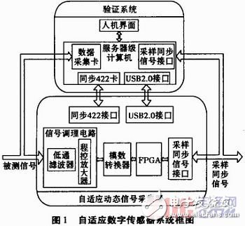
At the heart of the acquisition system is an FPGA-based controller, which ensures fast, real-time processing and flexible control. This makes the system highly responsive to varying input conditions.
The experimental verification system works in tandem with the acquisition system, collecting and verifying the measured signals to ensure accuracy. It also restores the collected data back to its original form for comparison. This system is built around an industrial-grade computer, equipped with a high-speed RS422 communication card and an analog data acquisition card, enabling rapid, synchronized, and large-capacity data handling.
1.2 Programmable Amplifier DesignTo capture small signals effectively, the programmable amplifier plays a key role in scaling the input voltage according to the signal amplitude. The design uses AD8251 and AD8253 in cascade, as shown in Figure 2. The input signal is applied to the "IN+" terminal of the programmable gain amplifier (PGA), and the output is taken from the "OUT" terminal.
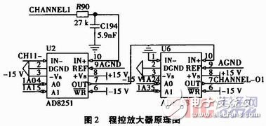
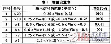
The AD8251 offers gain options of 1, 2, 4, and 8, while the AD8253 provides gains of 1, 10, 100, and 1000. Together, they allow a wide range of gain combinations, including 1, 2, 4, 8, 10, 20, etc. The gain is controlled through four digital inputs (1A0, 1A1, 1A2, 1A3), and the appropriate gain setting is chosen based on the input signal range, as detailed in Table 1.
The automatic gain switching module is a critical part of the adaptive digital sensor. Implemented within the FPGA, it automatically selects the optimal gain based on the amplitude of the incoming analog signal. This ensures sufficient resolution and accuracy in the measured values.
During system startup, the internal gain control unit continuously compares each sampled point from the ADC. If the voltage exceeds a threshold, it moves to a higher threshold level; otherwise, it checks lower thresholds. Based on this, the corresponding gain is selected.
The workflow of the programmable gain amplifier is depicted in Figure 3.
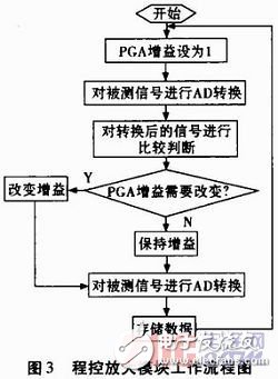
Before each sampling, the PGA is set to a gain of 1. After the ADC conversion, the gain is adjusted accordingly. The signal is then re-sampled, and the data is stored for further analysis.
3. Dynamic Testing of the Adaptive Digital Sensor 3.1 Test Principle, Method, and ProcedureThe test principle involves the adaptive digital sensor automatically adjusting the gain of the programmable amplifier based on the output voltage of the acceleration sensor. It then collects and stores the signal, uploading the data to the verification system for comparison and validation. The verification system synchronizes the collected data and restores the signal to its original form for analysis.
The testing method involves placing the acceleration sensor on a vibration table and recording its output using a multimeter, the adaptive digital sensor, and the verification system. The performance of the adaptive sensor is evaluated based on these results. Each test is conducted at a temperature between 20°C and 25°C, with a 30-minute preheating period before starting.
The test procedure includes:
- Placing the acceleration sensor on the vibration table and setting the frequency to 1 kHz. The amplitude of the acceleration signal is adjusted according to the set parameters to change the sensor’s output.
- Applying the acceleration signal to the test rig based on the rotation speed of the ion fan. The sensor’s output is recorded using a multimeter, while the adaptive digital sensor and verification system collect high-resolution data.
- The verification system restores the sensor’s output voltage signal based on the data collected by the adaptive digital sensor.
The specifications of the accelerometer used are as follows:
- Range: ±5000 g
- Sensitivity: 1.098 mV/g
The hydrogel Screen Protector has super ductility and shrinkage, has a strong and effective self-repair function, impact resistance, durability, better toughness, and has a certain buffering effect on sharp objects. The use of hydrogel film can adapt to the contours of any device, so it can be attached to curved screens and rounded edges. The full-coverage screen protector can perfectly fit your screen and provide maximum protection.
The 0.14mm ultra-thin thickness is more sensitive to the touch, and the ultra-thin design gives you a bare-metal experience. The oleophobic and waterproof coating prevents fingerprints and dust, makes the hydrogel screen protector easy to clean, and makes your phone look more beautiful.
Hd Clear Hydrogel Protector Sheet,Anti Blue-Ray Hydrogel Protector,Matte Hydrogel Film,Privacy Hydrogel Film
Shenzhen TUOLI Electronic Technology Co., Ltd. , https://www.tlhydrogelprotector.com