Abstract: This paper proposes a design scheme of digital FM radio based on WinCE 6.0, introduces the system design flow based on WinCE 6.0 and the characteristics of digital FM radio chip Si4730, and analyzes the driver and application under WinCE6.0 in detail. The design methodology is verified by a hardware platform based on the S3C2440. The solution has the advantages of high reliability, low power consumption, and beautiful interface.
Keywords: WinCE6.0; Si4730; I2C bus driver; S3C2440
This design utilizes the digital radio chip Si4730 to provide a good solution for integrating the FM function of the intelligent system based on WincE6.0. The solution realizes functions such as full-frequency manual and automatic search.
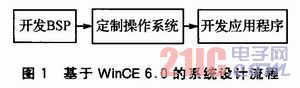
1 The system design flow based on WinCE6.0 is shown in Figure 1. The system design based on WinCE 6.0 is generally divided into three processes: designing BSP packages for different hardware platforms, BSP including Boot-loader, OAL and driver; For the needs of the system, use Platform Builder for CE 6.0 to select the appropriate components, build the operating system and export the SDK; develop the application under the support of the SDK.
This article refers to the address: http://
WinCE 6.0 has had a big change in development tools compared to its earlier versions. Platform Builder is not a separate release tool, and Platform Builder 6.0 has become Visual Studio. A plugin for Net 2005, so in Visual Studio. WinCE6.0 system customization, driver development and application development can be completed in the Net 2005 integrated development environment.
2 digital radio chip Si4730
2.1 Introduction to Si4730 Si4730/31 is a highly integrated AM/FM radio chip from Silicon Labs. The schematic diagram is shown in Figure 2.
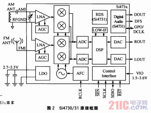
The Si4731 features RDS/RBDS functionality and a digital audio interface. The Si4730/31 and its peripheral circuits require only 15 mm2 without the antenna. It is very versatile, including automatic search, automatic calibration, digital tuning, adaptive noise suppression, etc. These features are ideal for portable devices. Since the RDS/RBDS function is not required, the Si4730 chip is used here.
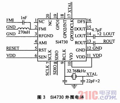
2.2 Si4730 Control Interface The peripheral circuit of the Si4730 is very simple, as shown in Figure 3. The Si4730 offers three control modes: 2-wire mode (compatible with I2C bus), SPI mode, and 3-wire mode. The chip determines the mode by which the GP01 and GP02 pins are in the rising state of the RST pin. When the GP01 and GP02 are left floating, the Si4730 is in 2-wire mode. When the SEN pin is tied high, the device address is 0xC6H; when connected low, the address is 0x22H.
3 Interface circuit and driver design The hardware platform of this design adopts S3C2440 processor, which has completed the development of BSP package and the transplantation of WinCE 6.0 operating system.
3.1 Design of the interface circuit Since the S3C2440 has an I2C interface, it is only necessary to interconnect it with the I2C interface of the Si4730. The reset pin RST of the Si4730 is connected to the GPB5 pin of the S3C2440.
3.2 Driver Design The driver consists of two parts: the driver of the I2C bus and the driver of the GPIO port. The I2C bus driver is used for communication between the operating system and the Si4730. The driver for the GPIO port is used by the application to control the reset of the Si4730.
3.2.1 Commands of Si4730 There are two commands for Si4730: one is control command, such as tuning to a certain frequency, automatic search, etc.; one is attribute command, such as setting the intensity threshold of the received signal and the output volume. Wait. Commonly used commands are as follows:
1 Power-on (POWER_UP), the command format is {0x01, 0xd0, 0x05}.
2 Get the chip information (GET_REV), the command format is {0x10}.
3 Tuned to a certain frequency (FM_TUNE_FREQ), the command format is {0x20, 0x00, ARG2, ARG3, 0x00}. ARG2 and ARG3 are hexadecimal numbers of the frequency, for example, 102.3 MHz, then ARG2 is 0x27, and ARG3 is 0xF6.
4 Automatic search (FM_SEEK_START), the command format is {0x21, 0x0c).
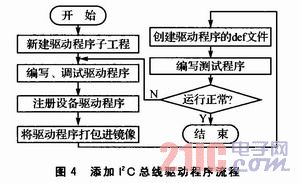
3.2.2 Implementation of I2C Bus Driver The I2C bus driver is developed using the design method of the stream interface driver. The stream interface provided by the I2C bus driver to the operating system is I2C_Init(), I2C Open(), I2C Close(), I2C Write(), I2C Read(), I2C_IOControl(), etc., and the application calls CreateFile(), WirteFile( ) and interface functions such as DeviceloControl() to access the device. The process of adding an I2C bus driver to the compiled WinCE6.0 image project is shown in Figure 4.
1 Add a subproject. In the Solution Explorer window of the mirror project, right-click Add New Subproject to create a new subproject.
2 Write the I2C bus driver. Create a new I2c under Source files. The source file of c, and write the driver code in the file, the main content of the driver is to implement the stream interface function. The implementation function for reading the I2C bus is BooL_WRITE_IIC (UINT32 slvAddr, UINT8 n, UINT8*data). The implementation function for writing the I2C bus is BooL READ_IIC (UINT32 slvA-ddr, UINT32 addr, UINT8 n, UINT8*data). The role of I2C_IOControl() is to pass I/O control commands to the device, in which the control of the Si4730 is implemented. Some of the code is as follows: 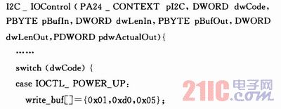
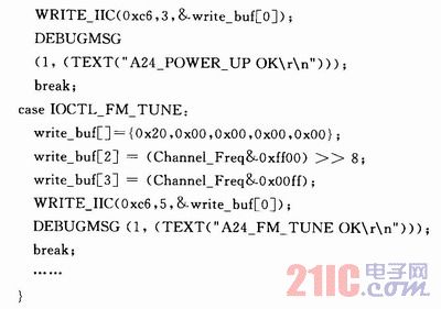
3 Register the device driver in the registry. Open the platform. Reg file, add registration information to it as follows: 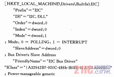
4 Package the driver into the image. Open the platform. Bib configuration file, add the following code:
I2c. Dll$(_FLATRELEASEDIR)\I2c. Dll NK SHK
5 Create a driver def file. The project needs to use the def file to export the corresponding function. The part of the file is: 
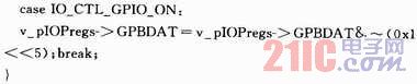
3.2.3 Implementation of GPIO Driver The Si4730 requires a reset signal when it is working. The S3C2440 GPB5 port is used for control. Set the register GPXCON as the output function in the driver, and set the value of the register GPXDAT to 0 or 1 to control the output port to be low level or high level. The relevant code is as follows: 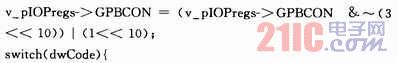
4 application design
4.1 Function Implementation The function of the application is to call the driver's stream interface function to control the Si4730, thus implementing the FM function. The APIs that need to be used in the application layer are CreateFile(), Devicelo Control(), ReadFile(), and WriteFile(). For the parameter description of the function, refer to the help file of Visual Studio 2005.
The program first uses CreateFile() to open the device handle:
I2Cdriver=CreateFile(L"I2C:", GENERIC_READ|GENERIC_WRITE, 0, NULL, OPEN_EXISTING, 0, NULL);
Then you can use DeviceIocontrol (), ReadFile (), Write File () and other API functions to control the device, such as the implementation of tuning:
DeviceloControl(I2Cdriver, IOCTL_FM_TUNE, NULL, 0, NULL, 0, NULL, NULL);
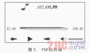
4.2 Interface Design A good interface is an important part of the application. As shown in Figure 5, the interface should have the following parts: play, frequency up-tuning, frequency down-tuning, volume control, and so on.
We carry various sd controller and software to fully customize your led lighting effects using iseeled's stand alone controller. You can get the synchronous and timing to show effects by the Gps Led Controller . Regard to our sd controller and stand alone controller, you can use them to control the LPD6803, LPD8806, LPD6813, LPD1882, LPD1889, DMX512 Led Pixel Lights and so on. It's easy for you to operate and edit led programmes with our corresponding led software and save the led effects on the sd card to show nice and vivid lighting effects.
Photo show of Sd Card Led Controller:

Sd Card Led Controller,Sd Led Controller,Dmx Sd Card Control,Rgb Led Controller With Sd Card
Shenzhen Iseeled Technology Co., Ltd. , https://www.iseeledlight.com