1 Introduction
The robot line inspection refers to the use of the robot to carry the detection communication instrument along the whole line, and the robot completes the detection of the line operation failure and the inspection of the hidden danger of the safety accident, and transmits the detected information to the ground in real time, and analyzes it by the ground. deal with. In the normal ground operation, a small battery timing replacement method is generally adopted. However, high-voltage transmission lines are distributed in the wild, crossing mountains and lakes, and when patrolling robots operate, energy consumption is large, and there is no power source available for charging at the scene, and frequent replacement of batteries during the line inspection process causes inconvenience, and this factor will Greatly limit the wide application of line-of-sight robots.
To this end, this paper studies the Power Supply system that supplies power to the robot by means of induction power.
2 system structure
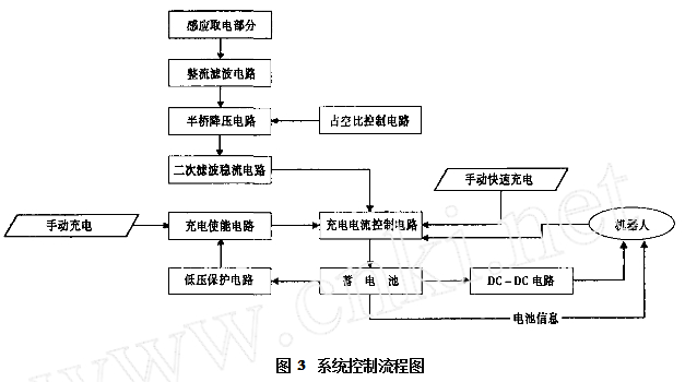
In order to achieve the above purpose, the iron core and the coil are designed to obtain electric energy from the high-voltage line, and the obtained electric energy is converted into a steady current source through the Switching Power Supply, and the nickel-hydrogen battery is charged by the charging enable circuit, and at the same time, the charging control circuit monitors the battery voltage. Control the charging mode, whether it is charging, whether it is stopped, and transmit the information to the main control system of the patrol robot.
3 working principle
According to the electromagnetic field theory, there is an alternating magnetic field in the high-voltage transmission line around the working state. According to the law of electromagnetic induction, the circuit in the magnetic field will generate an induced current. Under the premise that the transmission line is infinitely long, the magnetic flux line of the magnetic field generated by the transmission line is a concentric circle around it. For example, the current in the transmission line is I1. According to the Ampere loop theorem, the magnetic field strength at any point from the distance of the transmission line can be pushed out: H=I/2 πr(A/m)(1)
The magnetic induction is: B = μI / 2πr (T) (2)
The aspect of B is tangent to the circle centered on the wire and perpendicular to the plane of the wire. If the robot is treated as a resistor R, a current I2 will be generated in the loop composed of the induction coil and the robot. The equivalent diagram is shown in Fig. 1.
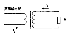
Figure 1 circuit diagram of the electrical device
The core of the research on robot power system is how to efficiently convert the magnetic field energy around the transmission line into electrical energy. The key part is the design of the core and coil.
4 power system components
4.1 core and coil
The characteristics of the iron core and the size of the body have a great influence on the output power of the induction device. As shown in Fig. 2, the high-voltage transmission line can be regarded as an initial winding with only one turn. According to the law of electromagnetic induction, the effective value of the induced electromotive force at both ends of R is : 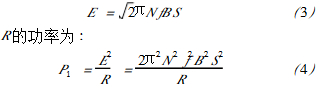
Ignoring the excitation current, I1 and the current I2 flowing through R satisfy I1≈NI2. According to the induced current, the power of R is: 
It can be seen from equation (4) that due to the limitation of the robot volume, in the case of a certain S, the selection of a suitable core material to increase the magnetic induction strength is a way to increase the output power. The current in a high-voltage transmission line is constantly changing due to the load, and the peak current is hundreds of times the valley current. Within such a large variation, in order to ensure continuous power supply to the robot, the power take-off device must achieve higher energy at a lower current and increase as the current increases. Corresponding to the iron core, it is required to have a high initial magnetic permeability and a high saturation magnetic induction. Among the soft magnetic materials currently used, since the silicon steel sheet has a large saturation magnetic induction strength and a lamination coefficient, a large power can be obtained, so it is taken as a core material.
In order to avoid magnetic field loss, the core should be a whole to ensure that there is no air gap in the magnetic circuit. However, since the high-voltage transmission line has no break point, at the same time, the robot needs obstacles such as hanging objects and counterweights during the traveling process. The core must be designed in two parts that can be separated. When the two parts are in normal operation, they must be separated by a robot.
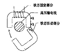
Figure 2 Schematic diagram of the iron core structure
It can also be seen from the equations (1) and (2) that the power taken by the power take-off device is simultaneously affected by the number of turns of the coil. If the energy harvesting device is to obtain the maximum energy, P1 and P2 should reach the maximum value at the same time. In this case, P1=P2 should be satisfied.
At this point, the power take-off can achieve maximum power. This relationship was introduced with the exception of magnetic flux leakage, air gap, and field current. To verify its accuracy, we tested the coil turns individually. During the experiment, the transmission line current I1=210A. At this time, according to the magnetization curve of silicon steel, it can be found that B≈1.8T, the load equivalent resistance R=800 Ω, the current frequency f=50Hz, and the theoretical calculation value is N=738. The test data is shown in Table 1.
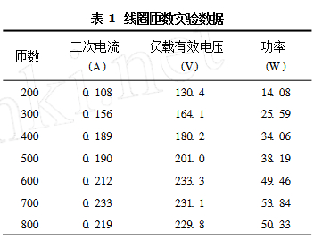
It can be seen that at around 700 ,, the power reaches a maximum value, which is close to the theoretical value.
4.2 charging and control circuit
The electric energy obtained by the iron core and the coil from the high-voltage line is converted into a steady current source through the switching power supply, and the nickel-hydrogen battery is charged by the charging enable circuit, and the charging control circuit monitors the battery voltage to control the charging mode, whether to charge, whether to stop or not. And transmit the information to the main control system of the patrol robot. Figure 3 is the system control flow chart.
4.2.1 Switching power supply circuit
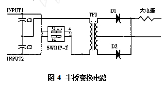
The switching power supply uses a half-bridge conversion circuit for step-down, as shown in Figure 4. For convenience of explanation, the switch control of the FET is replaced by two switches (swdip22), and the switches S1 and S2 are alternately turned on. When S1 is turned on, S2 is turned off, and then vice versa. Under steady-state conditions, when C1 = C2, when S1 is turned on, 1/2VS on C1 is applied to the primary coil, and the secondary winding voltage turns on D2. After the time set by the duty cycle, S1 is turned off, S2 is turned on, and the secondary winding voltage turns on D1. The switching control of the FET is controlled by the 9,10,12 pins of the KA7500B chip. The control circuit uses the transformer coupling to drive the MOSFET, and drives the BG3, BG4, BG7, and BG8 to form a bridge push-pull power amplifier circuit. When the high level is output through the 9 pin, the 10 pin is low, and BG4 and BG7 are turned on. Transformer TF1 flows through the forward current. The voltage on the primary winding of transformer TF1 is reversed and is half the total voltage from the rectifier bridge, as shown in Figure 5.
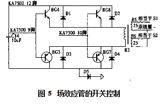
When the 10-pin output is high, the 9-pin is low, and BG8 and BG3 are turned on. Transformer TF1 flows through the reverse current. The voltage on the primary winding of transformer TF1 is positive and the same size is half of the total voltage coming from the rectifier bridge.
4.2.2 Charge Control Circuit
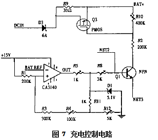
The designed charging circuit must stop charging when the voltage reaches the peak voltage to prevent the battery from being overcharged; and when the charging is completed, the C/102C/15 should be used for supplementary charging to prevent weak polarization due to the battery. The charge enable circuit is shown in Figure 6. The SR24 is the relay, the CTL+, CTL- is connected to the output of the coil, and the 78L15 provides a stable 15V supply for the op amp. The core of the enabling circuit is the CA3140. This circuit cannot use an open-loop comparator circuit because the NiMH battery also needs to work during charging. The characteristics of the dv dt may vary greatly. The ca3140 is connected in the form of a schmitt trigger.
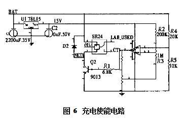
Figure 7 shows the charge control circuit. The CA3140 consists of a schmitt trigger. The main function of the Zener diode is to stabilize the amplitude of the output voltage and provide a suitable operating point for the triode. R5 is a protection resistor that acts as a current limiter. Two optical compartments are used to force the fast charge enable and fast charge detection to provide charging information for the robot.
When the robot passes the obstacle, the motor provides more power, and the charging current may be less than the discharge current. To protect the battery from over-discharging, the protection circuit is designed as shown in Figure 8.
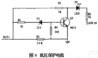
When the voltage across the battery is lower than 24V, due to the nonlinearity of the Zener diode, the potential of the base of the three-stage tube Q1 tends to 0, Q1 is reversed, and the current flows through R5 and D2 into the optical partition D3, generating a LOW signal. The robot stops charging. When the battery voltage is higher than 24V, Q1 is turned on, and the current flows from R5 to the transistor Q1.
The robot needs to output 32V, 7A; 24V, 4A; 12V, 3A; 5V, 2A four-way voltage, select DC/DC module power supply, convert the voltage at the battery output terminal into the above four voltages.
5 Conclusion
In this paper, the theoretical analysis and practical design of the robot power supply system are carried out. The influences of the parameters of the induction power take-off device (magnetic properties of the core, geometric size, number of turns of the coil, etc.) on the power take-off are theoretically introduced. The relationship, according to the theoretical analysis results, carried out the corresponding test; at the same time, the power supply system control circuit and charging circuit working principle are introduced in detail. The development of this system is a good solution for the power supply problem of high-voltage operation equipment.
More robot technical data, circuit diagrams and DIY design can be found in this issue of Designs of week - when Chinese manufacturing encounters robotics, design thinking please keep up!

For 24 Wall Charger with different plugs for choose, the input voltage 100V~240V 50/60Hz suits for worldwide use. which are popularly used for HD player, DVD, LCD TV, surveillance camera, LED display, LED light, USB hub etc.
24V Wall Mount Adapter has common 24V 500MA, 24V 1A, 24V 2A etc, the dc plug size has 5.5*2.5mm, 5.5*2.1mm and so on,
Yidashun's wall charger has intelligent protection system, to support over-current, over-voltage , short-circuit, overcharge protection etc, and Yidashun's wall mount Power Adapter has smart IC solution, high efficiency, energy saving and small ripple etc advantages.


24V Wall Charger,Tablet Charger,24V Wall Battery Charger,24V Wall Power Charger
Shenzhen Yidashun Technology Co., Ltd. , https://www.ydsadapter.com