1. Application of Master Control Instructions to Program Branches A and B
(1) Control Requirements:
The A block should flash the lamp once per second, while the B block should flash every two seconds. When button X0 is turned on, the A block is activated, causing Y0 to flash once a second. When X0 is turned off, the B block is executed, and Y1 will flash every two seconds.
(2) Input/Output Signal Definitions:
Input: X0 – Button; Output: Y0 – A Lamp, Y1 – B Lamp
(3) Reference Program (Ladder Diagram) is shown below:
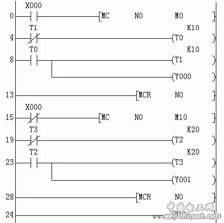
(4) Program Analysis:
When X0 is active, timers T0 and T1 operate normally, creating an oscillator. The waveform from T0 (connected to Y0) is a square wave with a 2-second period and 50% duty cycle. At this time, T2 and T3 are reset, keeping Y1 inactive. When X0 is off, T2 and T3 become active, forming another oscillator that controls Y1 with a 4-second period and 50% duty cycle, while T0 and T1 are reset, keeping Y0 inactive.
(5) Thinking:
Run the program on the machine and observe: What happens to the output states when X0 changes? Does the system retain the previous state of the outputs?
2. Application of Jump Instruction in Branch A and B Control Programming (Modified Based on Master Control Instructions)
(1) Control Requirements:
Same as above: A flashes once per second, B once every two seconds, depending on the state of X0.
(2) Input/Output Signal Definitions:
Input: X0 – Button; Output: Y0 – A Lamp, Y1 – B Lamp
(3) Reference Program (Ladder Diagram) is as follows:
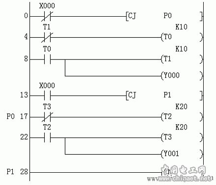
(4) Program Analysis:
When X0 is on, the program jumps directly to END and restarts. Timers T0 and T1 are scanned, producing a 2-second square wave on Y0. At this point, T2 and T3 are not scanned and maintain their previous state. When X0 is off, the program jumps to P0, scanning T2 and T3, which produce a 4-second square wave on Y1. T0 and T1 remain unchanged.
(5) Thinking:
1. Run the program and observe: Does the output state persist when X0 changes? Compare the behavior of jump and master instructions.
2. Explain the role of label P1. Move P1 to the start of the program and run it—what happens? Why?
3. Using the CJ Command for Motor Jog and Self-Locking Control
(1) When the selector switch is in the jog position and the start button is pressed, the motor runs immediately. When the button is released, it stops.
(2) When in automatic mode, pressing the start button starts the motor. Releasing it causes self-locking. Pressing the stop button turns it off immediately.
4. Subroutine Call Programming – Pay Attention to Coil State Changes After Calling
(1) Program Running Process:
1. Without subroutine call: X0=OFF, X1=OFF, X2=OFF → Y0 flashes once, Y1–Y6 OFF.
2. With only subroutine P1 called: X1=ON, X0=ON → Y0 still flashes, Y1 ON. After X1=OFF, Y1 remains ON. When X0=ON again, Y1 turns OFF.
3. Continuously calling P1 and P2: X2=ON, X0=ON → Y0 flashes once, Y5 and Y6 flash twice. Observe coil states after each call.
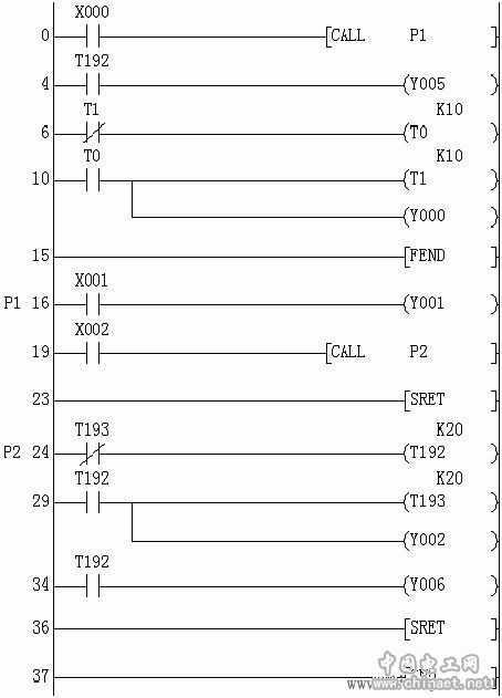
5. Application of Interrupt, Loop, and Refresh Timer Commands – Focus on Timer Effects in Interrupt Service Routines
(1) Program Execution Steps:
1. Execute loop program: X10=OFF, monitor M0–M2 and D0. When D0 overflows, observe how Y0 reacts.
2. First interrupt: X11=ON, X3 jogged → Y2 and Y1 turn on, Y3 stays off until next interrupt.
3. Second interrupt: X11=ON, X3 jogged again → Y3 turns on.
4. X11 turns OFF → All outputs turn off.
Note: Even if T192 is set to K=0, Y3 won’t activate during the first interrupt.
(2) Reference Ladder Diagram:
(3) Thinking:
Run the program and answer:
1. How does adding or omitting the 'P' in CALLP1 affect the program’s execution?
2. Analyze the behavior of timers T192 and T193 when X0 is toggled.
O.D80MM Hydraulic Dc Motors,O.D80MM Hydraulic Dc Motor,O.D80MM Dc Hydraulic Pump,O.D80MM Dc Hydraulic Pump Motor
Wuxi Jinle Automobile Motor Factory , https://www.wxjldj.com