The AD604 is a low-noise, high-precision, dual-channel variable gain amplifier developed by Analog Devices. One of its key advantages is that the decibel (dB) value of the gain is directly proportional to the control voltage, making it particularly well-suited for time gain compensation (TGC) circuits in ultrasonic instruments. This article provides an overview of the AD604's features, internal structure, and typical applications, with a focus on its use in ultrasonic signal attenuation compensation.
Compared to similar devices, the AD604 stands out for its ultra-low noise performance, high precision, and continuous gain adjustment capability. In medical ultrasonic systems, the TGC circuit requires the gain to increase exponentially with the control voltage, meaning the dB value should be linear with respect to the control voltage. The AD604 meets this requirement perfectly, effectively reducing the dynamic range of signals sent to the analog-to-digital converter (ADC). Key characteristics of the AD604 include:
- Ultra-low input noise, with both voltage and current noise at their minimum at maximum gain.
- A bandwidth of 40 MHz (-3dB).
- Two independent gain channels, where the gain in dB is proportional to the control voltage.
- Programmable gain for each channel: when the preamplifier is set to 14 dB, the gain can be adjusted from 0 to +48 dB; when the preamplifier is set to 20 dB, the gain ranges from +6 to +54 dB.
- Input resistance of 300 kΩ.
- A variable gain range of 20–40 dB/V.
- Stable gain despite temperature and supply voltage variations.
- Single-ended unipolar gain control.
- Automatic power-off when the gain drops below a certain threshold.
- Directly drives the ADC.
**Pin Function Description**
The AD604 is available in a 24-pin package, including DIP, SSOP, and SOIC options. The pinout is shown in Figure 1. Below is a description of each pin’s function:
- **PAI1/PAI2**: Preamplifier positive input.
- **PAO1/PAO2**: Preamplifier output.
- **FBK1/FBK2**: Preamplifier feedback terminal.
- **COM1/COM2**: Signal ground. Connecting it to the positive supply turns off the preamplifier channel.
- **-DSX1/-DSX2**: Differential attenuator signal input negative terminal.
- **+DSX1/+DSX2**: Differential attenuator signal input positive terminal.
- **VGN1/VGN2**: Gain control input and power-off terminal. When grounded, the attenuator channel is disabled; otherwise, increasing the positive voltage increases the gain.
- **VREF**: Gain control reference for both channels. At +2.5 V, the gain is 20 dB/V; at +1.67 V, it is 30 dB/V.
- **VOCM**: Common-mode voltage control for the output signal, used to set the DC midpoint of the output signal.
- **OUT1/OUT2**: Signal output terminals.
- **VPOS/VNEG**: Connect to the positive and negative power supplies.
- **GND1/GND2**: Ground connections.

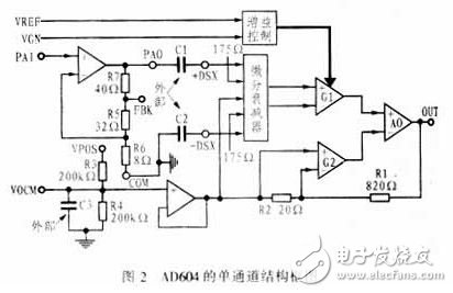
**Internal Structure and Working Principle**
The AD604 is a dual-channel variable gain amplifier, with each channel consisting of a low-noise preamplifier and a variable gain amplifier (XAMP). The XAMP includes a high-precision controlled differential attenuator, a gain control unit, a fixed-gain feedback amplifier, and a VOCM common-mode voltage control unit made up of discrete components R3 and R4. The internal structure is illustrated in Figure 2.
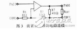
**2.1 Preamplifier**
Each channel of the AD604 includes a high-performance preamplifier, which can be adjusted between +14 dB and +20 dB using an external resistor on the feedback loop. The internal circuit of the preamplifier is shown in Figure 3, where R5, R6, and R7 are the gain control resistors. The specific gain is determined by the resistance between FBK1 and PAO1.
Hybrid Fiber Coaxial HFC Equipment
catv trunk amplifier,optical receiver,Optical Transmitter,FTTH Optical Node,indoor optical receiver
Shenzhen Runtop Technology Co.LTD , https://www.runtoptech.com