In recent years, to enhance the positioning accuracy of the system and meet the evolving demands of the industry, various control methods and strategies have been explored. A significant amount of research has been conducted on pneumatic servo systems. When it comes to new assignments or product changes, it is relatively easy to modify or redesign parts. By reprogramming the system, the position can be adjusted quickly, reducing installation and conversion costs. The Modular Production Training System (MPS), developed by the German company FESTO, is a simulation-based automation production unit tailored for modern industrial needs. It replaces repetitive or high-precision tasks, meeting the requirements of advanced products and automated equipment upgrades.
Currently, several Chinese manufacturers have started to imitate some MPS products from abroad. Examples include the "MPS/FMS Modular Production Training System" produced by Shanghai Yingjis Automation Technology Co., Ltd., and the "Yalong YL-MPS Modular Production Training System" from Zhejiang Yalong Teaching Instrument Co., Ltd. This paper focuses on the MPS equipment provided by Shanghai Yingjis Automation Technology Co., Ltd., combined with the specific needs of the laboratory (a nationally recognized key construction laboratory supported by central funding). It presents a complete PLC-based control solution for the loading detection unit of the MPS system.
**Structure, Function, and Pneumatic Control Circuit of the Feeding Detection Unit**
The feeding detection unit serves as the starting point in the MPS system, supplying raw materials to other units within the system.
**2.1 Structure and Function of the Feeding Detection Unit**
The feeding detection unit consists of an I/O wiring port, a tray module, a gas source processing component, a workpiece detection component, a lifting module, and more. Its main function is to automatically retrieve the workpiece placed in the tray as needed, detect its color (black or white), lift it to the output station, and wait for the next unit to take it.
**2.2 Pneumatic Control Circuit of the Feeding Detection Unit**

*Figure 1: Feeding detection unit pneumatic control circuit*
The actuator of the feeding detection unit operates through a pneumatic control system. The directional control valve can be manually operated or controlled via electromagnetic means. In the schematic diagram, 1A represents a double-acting lifting cylinder, 1Y1 is the solenoid valve signal for the double-acting cylinder, and 1B1 and 1B2 are magnetic inductive proximity switches. The pneumatic control circuit is illustrated in Figure 1.
**Design Scheme of the PLC-Based Control System for the MPS Loading Inspection Unit**
The design of the PLC-based control system for the loading detection unit involves several key tasks. Once the power and air supply are turned on, the PLC runs and performs a reset action, lowering the workpiece platform into position. The tray then rotates to output the workpiece. When the tray detects a workpiece on the platform, it stops rotating, the lifting cylinder activates, and the platform is raised to the output station. The color of the workpiece is detected and recorded. Pressing the "Special" button indicates that the workpiece has been removed. The platform then lowers back to its original position, and the tray continues to rotate, repeating the cycle.
**3.1 Input and Output Addresses for the PLC in the Feeding Detection Unit**
The mapping between the PLC input/output signals and the actuators is shown in Table 1.
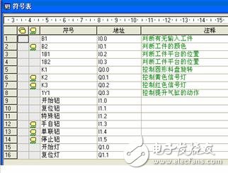
*Table 1: Correspondence between PLC input and output and actuator*
**3.2 Writing and Debugging the Program**
The manual control program block diagram for the feeding detection unit is shown in Figure 2.
*Figure 2: Manual control block diagram of the loading detection unit*
The PLC ladder program for the feeding detection unit is presented in Figure 3.
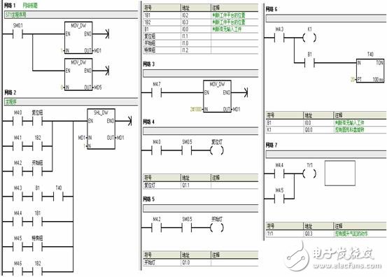
*Figure 3: PLC ladder program of the loading detection unit*
After debugging, the program successfully completes the control tasks of the unit.
**Conclusion**
This paper provides a detailed analysis of the structure, function, and pneumatic control circuit of the feeding detection unit. It then outlines the design and implementation of the PLC control system for the unit. First, the input and output distribution table was created, followed by the development of the program flowchart and ladder diagram. Finally, the system was tested and verified, confirming the feasibility of the secondary design and implementation of the PLC-based MPS loading detection unit control system.
Two key conclusions were drawn:
(1) When designing control tasks for each unit, it is essential to write the actual control tasks based on the unit's basic functions. This ensures maximum utilization of its features while adhering to the mechanical design to avoid conflicts and potential damage to components.
(2) The efficient use of shift instructions, data transfer instructions, and the RS trigger instruction during ladder programming significantly reduces programming time and improves control performance. As a result, the PLC control system for the loading detection unit was quickly designed and implemented.
This battery is for replacing lead-acid battery, it has the standard appearance and size as well as capacity, but longer cycle life and high energy and good charge and discharge performance.
Capacity:100AH/150AH/180AH/200AH/250AH.
Voltage:12.8V, cycle life is more than 2000 times, also can customize the capacity.
Lifepo4 Battery,Lifepo4 Battery 12V,Solar Battery Pack,180Ah Lithium Mobile Battery,2304Wh Lithium Battery Power Bank,Lead Acid Replacement Battery
Enershare Tech Company Limited , https://www.enersharepower.com