This article explains the differences between analog and digital circuits on a PCB. To help everyone understand more clearly, I designed two circuits using ORCAD: one is a basic transistor-based analog amplifier, and the other is a digital oscillator circuit. Let's get straight to the point.
Below are the circuit diagrams with a single-point ground connection:
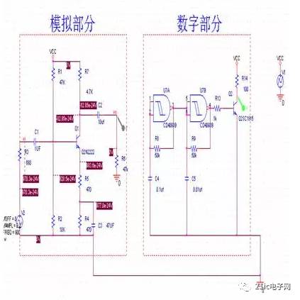
In reality, it’s not necessary to draw small grounding points like this in the schematic. I just did it for better visibility. You can see that the left side is the analog amplifier, while the right side is the digital oscillator. During simulation, the current in the digital part was too small, so I connected it to the first-level transistor.
Here are the waveforms of both circuits:
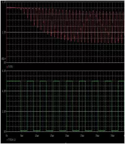
You can see that both waveforms look good with no distortion. The red line represents the amplified signal from the transistor, and the green line shows the oscillator waveform. Someone might wonder why the previous waveform didn’t look good—it’s because the actual power supply was simulated in ORCAD, which introduces some timing issues, making the signal very small.
You can also notice that there are small grounding points in both circuits, but they don’t affect the operation. Everything works normally together.
Now, here’s the circuit diagram without the grounding connection:
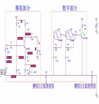
I used two resistors here to simulate the resistance of the PCB traces. Some of you might think this seems unrealistic, as PCB trace resistance isn’t usually 50 ohms. But I used larger values for clarity. In reality, it would be much smaller, but compared to high-frequency circuits, the wire impedance can sometimes be significantly lower than the inductive reactance, leading to such resistance values. This is how the digital circuit is connected behind.
Now, let’s look at the simulation waveforms again—will they be the same as before?
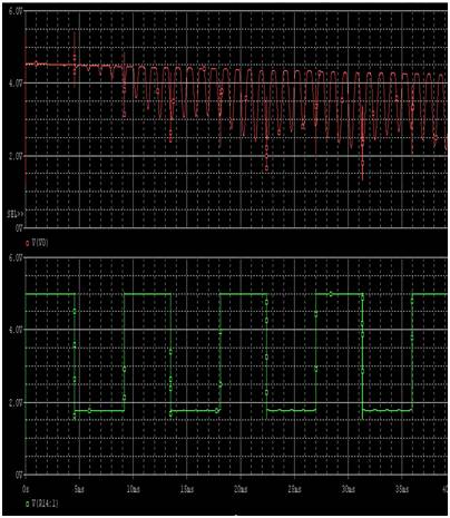
You can see that the analog amplifier’s waveform is now disturbed. Let me show you the individual signals:
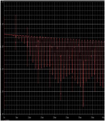
The distortion is quite noticeable. Now, here’s another waveform where the layout is closer to the power supply, so the interference isn’t as bad:
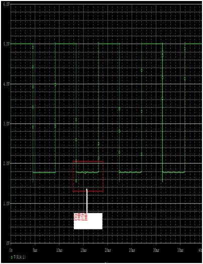
As you can see, the digital circuit is still being affected by noise. Let me show you an enlarged version:
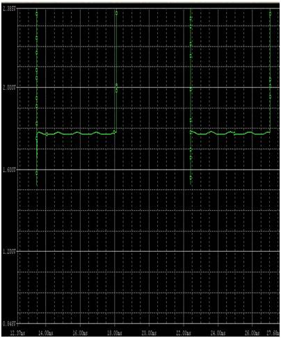
You can clearly see that the simulation has been disturbed. This demonstrates how important proper grounding and layout are when designing mixed-signal PCBs.
Our Musical Mug is good in quality and competitive in price. We are manufacturer and supplier of Musical Mug following your specific requirement. We are looking forward to your E-mail and establishing cooperative relationship with you! We would provide professional Musical Mug with good services for you!
Recordable Musical Mug, Recordable Music Mugs for Promotion, Promotional Music Mug
AST Industry Co.,LTD , https://www.astsoundchip.com