Abstract: A Nios II-based voice encryption transmission system is designed and implemented. The function modules for voice signal processing are introduced, including voice acquisition and playback module, G.729A-based voice compression and decompression module and AES-based data encryption and decryption module. Under the coordination of the control module, the voice data can be securely transmitted in the public telephone network through the MODEM, and the voice confidential communication is realized.
Due to the lack of confidentiality measures, telephone eavesdropping incidents continue to occur, seriously threatening personal privacy, military trade secrets, and even regional or national information security. Therefore, voice encryption transmission technology based on voice compression and data encryption has attracted attention. G.729A is a simplified scheme of G.729 (Conjugate Structure Algebraic Code Excited Linear Prediction Coding Scheme CS-ACELP), which reduces the computational complexity for real-time implementation. The National Institute of Standards and Technology (NIST) has conducted three rounds of screening in numerous block ciphers and selected the Rijndael algorithm as the Advanced Data Encryption Standard (AES).
Based on G.729A and AES, this paper designs a voice encryption transmission system combined with Nios II to encrypt the communication content, effectively preventing the leakage caused by the eavesdropping of the call content.
1 Overall structure
The voice encryption transmission system mainly includes a voice processing module, a voice transmission module, a control module and corresponding voice input and output devices. The voice module is composed of a voice collection and playback module, a voice codec module, and an encryption and decryption module. The overall design of the system is shown in Figure 1. The functions of each part of the system are as follows.
Schematic diagram of overall design of voice encryption transmission 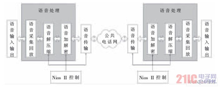
Figure 1 Schematic diagram of the overall design of voice encryption transmission
(1) Voice collection and playback module: This module implements voice collection and playback. On the one hand, this module receives the analog voice transmitted by the microphone, and generates digital voice through A/D conversion; on the other hand, the module receives the voice from the voice. The decompressed voice data from the codec is converted to analog voice by D/A conversion, and output by the speaker device.
(2) Speech codec module: The encoding and decoding of speech is to transmit high-quality speech at a lower rate by compressing and restoring speech. The speech codec includes an encoder and a decoder. The encoder processes the original digital voice information transmitted from the acquisition and playback module, analyzes the digital voice signal, extracts the voice parameters, and sends the compressed data to the data encryption module. The function of the decoder is to receive data from the data encryption and decryption module, and after decompressing the data, the data is restored to the original digital voice information, and then transmitted to the voice collection and playback module.
(3) Encryption and decryption module: The voice encryption and decryption module is the core to ensure the security of voice communication. The encryption and decryption module receives the data from the digital voice decompressor, encrypts it, and then sends it to the communication transmission module, and transmits the data to the public telephone network through the modem; meanwhile, the encryption and decryption module receives the data from the communication module, and After decryption, it is sent to a digital voice decompressor for decompression of the data.
(4) Communication transmission module: under the control of the control module, when the control module of the system side detects the dialing information or receives the request from the other party, it completes the interconnection with the other party; on the basis of establishing the connection between the two parties, the communication transmission module will be the data. Converted to data that can be transmitted over the public telephone network for the transmission of encrypted voice data.
(5) Nios II system control module: When the communication party initiates or receives a communication request, the Nios II system control module controls the coordinated operation of the entire system, so that the communication parties can communicate securely.
2 system design
2.1 hardware function module design
This design takes Nios II microprocessor as the core, realizes functions such as voice collection and playback, digital voice codec and encryption and decryption, and exchanges data through modem to realize encrypted transmission of voice. After research and analysis of the design, combined with the DE1 development board, the whole system hardware is divided into a voice processing module and a voice transmission module. The overall hardware structure block diagram of the system is shown in Figure 2.
System overall hardware structure block diagram 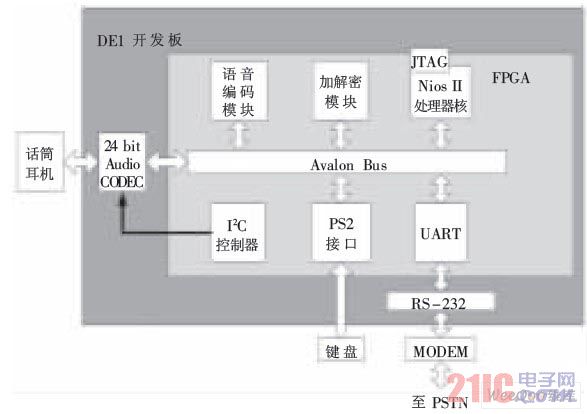
Figure 2 System overall hardware structure block diagram
2.1.1 Voice Capture and Playback Module
This module is the starting point and end point of voice-encrypted communication. The 24 bit CD-Quality Audio CODEC chip provided on the development board is used to complete the voice signal A/D and D/A conversion of the system. The WM8731 codec is packaged in the CODEC chip and has a sample rate of 8 kHz to 96 kHz. It is a low voltage, headphone-driven codec that provides stereo and single microphone audio inputs with reduced input noise, programmable volume control, and output voltage gain for electrical microphones. The WM8731 has 11 internal registers. The initialization and internal function settings of the WM8731 are implemented by the I2C control module to configure the 11 internal registers. In this design, WM8731 works in slave mode, the sampling frequency is set to 48 kHz, the converted data bit length is 16 bit, and the register parameter (hexadecimal) of WM8731 is set as shown in Table 1.
Table 1 Register Configuration Parameters 
Register configuration parameter
According to the characteristics and functions of the chip registers, the I2C control module is designed and connected to the Avalon bus of the system through SoPC Builder in the form of an IP core. The I2C control module writes the corresponding control information to the target register through the I2C_SDAT data port in the module to achieve the configuration of the WM8731 working state.
2.1.2 G.729A voice codec module
The G.729A processing speech frame based on the CELP coding model is sampled at 8 000 samples per second, corresponding to 80 samples per 10 ms, and the speech quality is equivalent to 32 kb/s ADPCM.
(1) Encoder
The working principle of the G.729A encoder is shown in Figure 3. In the pre-processing block, the input speech signal is first subjected to high-pass filtering and scaled down, and the LP filter coefficients are calculated every 10 ms for the pre-processed speech, and the LP coefficients are converted into line spectrum pair coefficients LSP, and LSP is The coefficients are quantized to 18 bits using predictive two-stage vector quantization (VQ). The excitation signal is selected using an Analytical Synthesis (ABS) search algorithm in which the error between the original and reconstructed speech signals is minimized based on the perceptual weighted distortion measure.
G.729A coding structure 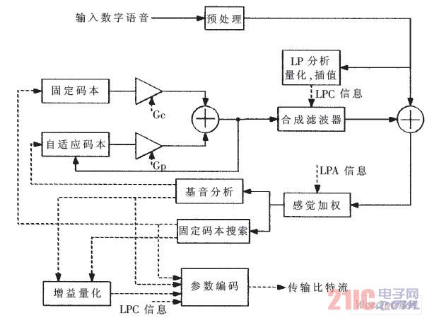
Figure 3 G.729A coding structure
Specifically, the error of the reconstructed speech and the pre-processed speech is searched for the smallest filtered error by the adaptive perceptual weighting filter, and the adaptive coefficient of the perceptual weighting filter is controlled by the unquantized LP coefficient. The excitation parameters (adaptive and fixed codebook) of G.729A are determined every 5 ms (40 samples) sub-frame. First, an open loop pitch delay is estimated once per 10 ms frame based on the perceptually weighted speech signal, and the LP residual signal is obtained by the weighted synthesis filter to obtain the target signal. The initial state of the filter is updated by filtering the error between the LP residual signal and the excitation. After obtaining the impulse response of the weighted synthesis filter, the closed-loop pitch analysis (finding the delay and gain of the adaptive codebook) can be performed using the impulse response and the target signal. The target signal is updated after considering the influence of the adaptive codebook for searching for a fixed codebook. The vector code is quantized with 7 bits after the adaptive codebook and fixed codebook search are completed. The memory value of the last filter is updated by the determined excitation signal.
(2) decoder
The principle of the G.729A decoder is shown in Figure 4. First, parameter labels are extracted from the received bitstream, and these labels are decoded to obtain encoding parameters corresponding to a 10 ms speech frame. These parameters are LSP, 2 fractional pitch delays, 2 fixed codebook vectors, 2 sets of adaptive codebooks, and fixed codebook gains. The LSP coefficients are interpolated in each sub-frame and converted into LP filter coefficients. Then, the following operations are performed for every 5 ms subframe: the adaptive codebook and the fixed codebook are multiplied by respective gains to obtain excitation; the LP synthesis filter is used to filter the excitation to obtain synthesized speech; the synthesized speech is included by one The adaptive post-filter of the long-term and short-time synthesis filters is enhanced and then subjected to high-pass filtering and scaling to obtain the final reconstructed speech.
G.729A decoder structure 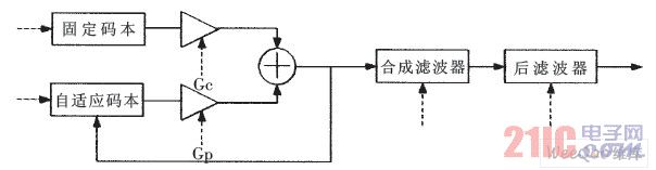
Figure 4 G.729A decoder structure
2.1.3 AES encryption and decryption module
The voice coded frame of G.729A is 80 bit/10 ms. According to the characteristics of frame encoding and transmission of voice, the block cipher is selected when constructing voice secret communication using the vocoder. In this paper, the advanced encryption standard AES is used to encrypt and decrypt the digital voice signal. In order to improve the AES encryption and decryption speed, the AES encryption and decryption process is designed as a custom instruction of Nios II.
(1) AES algorithm and hardware implementation
The working principle of the AES encryption module is as follows: under the control of the operation control module (Control), the plaintext to be encrypted is XORed with the initial circle key (AddRoundKey), and then Nr times iterative transformation is performed, except for the last circle (Nr circle) At the column blending transformation, each circle contains a four-step transform of a byte instead of a transform (ByteSub), a row shift transform (ShiftRow), a column blend transform (MixColumn), and a circle key addition (AddRoundKey).
The decryption process is similar to encryption. The ciphertext to be decrypted is XORed with the initial circle key (AddRoundKey), and then the Nr loop iterative operation is performed. Except for the last lap (Nr circle), the inverse column hybrid transform is omitted. The circle includes an inverse byte instead of transform (InvByteSub), a backward shift transform (InvShiftRow), an inverse column hybrid transform (InvMixColumn), and a circle key plus (AddRoundKey) four-step transform.
The voice coded frame of G.729A is 80 bit/10 ms, and the data required for encryption per second is about 8 Kbit. Therefore, in the case of satisfying voice encryption, this paper implements AES in a round-robin manner to save hardware resources. Its hardware encryption and decryption structure and its related control signals are shown in Figure 5.
AES hardware encryption and decryption structure 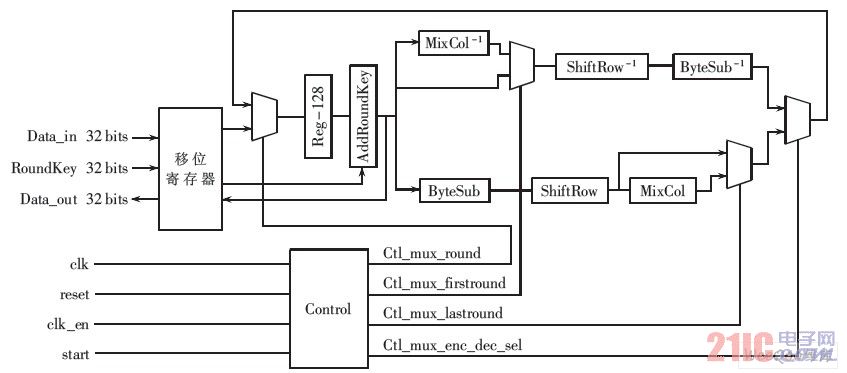
Figure 5 AES hardware encryption and decryption structure
(2) custom instruction logic
The internal hardware structure of the Nios II custom AES encryption instruction is shown in Figure 6. It can be seen from Figure 6 that the user-defined logic function (AES) is connected to the two inputs of the ALU and the output of the ALU. When using the Nios II custom command, the internal ALU operation of the Nios II will be abandoned to the user. The output of the custom logic is a valid result.
Nios custom logic instructions 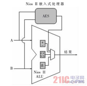
Figure 6 Nios custom logic instructions
The custom logic designed by the AES encryption and decryption module is completed in multiple clock cycles, using a multi-cycle custom instruction structure. The signal lines involved add clk, clk_en, reset, and start signals to dataa, datab, and result. Its instruction structure is shown in Figure 7.
AES custom instruction structure 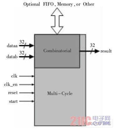
Figure 7 AES custom instruction structure
2.1.4 Communication Transmission Module
The communication transmission module uses MODEM to implement communication on the public telephone network PSTN. The PSTN network has a wide coverage, and the user can easily complete the docking and communication through the MODEM, which is very practical under the existing conditions.
MODEM is connected to DE1 through RS232 interface, connected to PSTN network through RJ45, and parses commands from Nios II control system to realize interconnection communication between the two parties.
(1) Working principle
The communication initiator uses the keyboard to dial the other party's number. The Nios II control system collects the dialing information and assembles it into the MODEM dialing AT command. The MODEM dials according to the command; the other party's MODEM receives the dialing information, sends an incoming call reminder, and turns on the voice processing function. Can communicate. The MODEM encapsulates the encrypted voice packet information to make it suitable for transmission over the PSTN network. The receiver MODEM receives the data packet, decapsulates it, and waits for the decryption process. In this system, MODEM works in half-duplex mode.
(2) Connection of MODEM and Nios II control module
The system needs to work normally, and the MODEM needs to interact with the Nios II control system. The signals used are as shown in Figure 8. The functions of each signal are as follows:
Communication transmission module 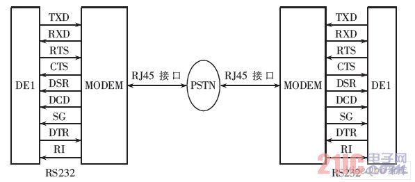
Figure 8 communication transmission module
DSR: Indicates that the MODEM power supply is connected and is ready for use.
RTS: Request to send a signal. The serial communication interface uses RTS to indicate to the MODEM the request to transmit data. This signal should control the MODEM to enter the transmission state or open the transmitter of the MODEM.
CTS: Clear the send signal, also known as the allowable transmission, is the response signal of the MODEM to the RTS, indicating that the MODEM is ready for transmission, and can output the transmitted data after receiving the CTS.
DCD: The data carrier detection signal indicates to the terminal device that the MODEM has received the data carrier signal on the communication link, notifying the other party that it is ready to receive.
TXD: Sends a data signal and sends the serial data to be sent by the terminal to the MODEM.
RXD: Receives a data signal and receives data sent serially from the MODEM.
SG: Signal ground, the signal ground of the connected equipment and communication equipment.
Due to the use of the Public Telephone Network (PSTN), two signals, DTR and RI, have been added to the above seven signals. The ringing indication RI informs the system that the MODEM has received the ringing call signal from the switching station; then the system starts the data ready DTR signal to the MODEM as a response to the RI. After the RI and DTR signals are hand-held, the MODEM can be "wired" to establish a communication link; when the data transfer is over, these signals should be reset to indicate "disconnection" and the communication link is released.
2.2 Nios II Control Module Design
The control module is developed using the Nios II IDE integrated development environment to control the entire system from dial-up (answering), voice acquisition, codec, encryption and decryption, transmission, and on-hook.
2.2.1 Establish communication
The dial-up keyboard is connected to the PS2 port of the DE1 development board, and interacts with the processor in an interrupt mode. When the control module receives the keyboard interrupt, it reads the user button information. According to the dialing information, the control module sends an AT command containing the dialing information to the MODEM through RS232, and the MODEM dials the corresponding number; after the answering party MODEM issues a ringing indication, the connection is established according to the command.
2.2.2 Voice Processing Control
The Nios II control module implements control of voice processing. Its main function is to read the result of a voice processing module and write it to the next function module according to the processing to be performed. The control module manipulates the I2C control voice acquisition and playback module to collect and digitize the voice, and then sends the digital voice signal to the codec module for encoding and decoding, and then calls the Nios II custom AES command to encrypt the data, and finally sends the data through the MODEM. On the receiving side, MODEM reads the voice data sent by the other party, the control module calls the Nios II custom AES command to decrypt the data, and then writes the decrypted data to the voice codec module for decoding, and finally calls the voice collection and playback module to restore. voice.
2.2.3 Communication End Control
During the call, if the communication interruption is detected or the communication party ends the communication information, a reset signal is issued to each function module, and the MODEM is controlled to be reset to the standby state, and the communication ends.
This design is applicable to government agencies, military, etc., which have a need for voice confidential communication, and is also suitable for commercial communications that require confidentiality. With this system, users can realize voice confidential communication like ordinary telephones. The design system is easy to use and can be connected via a modem and can be used on existing PSTN telephone networks. If the modem is modified to a wireless modulation scheme such as CDMA DTU, the user can also perform wireless secure communication.
This article refers to the address: http://
door opener keychain no touch,no touch keychain,no touch tool keychain,no touch keychain bulk, no touch keychain wholesale
Shenzhen Konchang Electronic Technology Co.,Ltd , https://www.konchang.com