LEDs for general lighting are just around the corner. LEDs have many advantages in general lighting systems, such as longer life and higher efficiency. However, LED technology faces some challenges. One of the challenges is how to produce high quality white light. White LEDs consist of a blue LED and a phosphor that moves the light output to other wavelengths of the spectrum. Many white LEDs do not produce a High Color Rendering Index (CRI), which is a measure of the ability of a light source to reproduce color.
By mixing two or more colors of LED light, a higher quality white light system can be obtained. In these multicolor systems, the light output of each color source drifts with time and temperature. Light sensors and small form factor microcontrollers (MCUs) can be used to maintain a specific color and Correlated Color Temperature (CCT). In this article, we'll take a closer look at sensors, required MCU resources, and software.
There are many affordable small light sensors on the market that provide information to the MCU for processing. Typically, the sensor has some optional color filters for measuring red, green, blue or white light (no filter). The light sensor output interface can be connected to the MCU in a series of ways. The photo-voltage sensor is connected to an analog-to-digital converter (ADC) through an output voltage. The optical frequency sensor provides a variable frequency output, and the output frequency is proportional to the amount of light. The pulse outputs of these sensors can be accumulated in the MCU timer to determine the level of illumination. Optical to digital sensors typically have a serial digital interface, such as I2C. Each type of sensor interface has unique advantages and requires different MCU resources. The system block diagram shown in Figure 1 shows a variety of MCU peripherals that are useful in color-tunable LED lighting designs.

In a complete closed-loop color control system, the MCU must read the color components from the light sensor, calibrate the light sensor output, and obtain the desired color by adjusting the output of each LED driver. LEDs require a constant current driver to maintain consistent light output. This can be achieved using a variety of driver technologies, including linear and switch mode solutions. The final choice depends on factors such as efficiency requirements, input voltage range, and the number of LEDs used.
The drive output can be controlled using different methods. First, the MCU can generate an analog reference voltage through a digital-to-analog converter (DAC) or a digital potentiometer. The reference voltage allows the driver output to vary between zero and maximum current. The MCU can also provide a PWM signal that is used to modulate the output of the driver. The PWM signal can be used to enable/disable the driver itself or to control the switch that disconnects the LED from the driver output. If PWM control is used, the selected PWM frequency is high enough so that the human eye does not notice any flicker.
The designer must determine the level of control resolution required by the color control system to select the MCU with the appropriate peripheral. For the photo-voltage sensor, the measurement resolution of the ADC on the MCU is important. The optical frequency sensor requires an MCU time base that is incremented by an external clock. Optical to digital sensors require a corresponding serial communication interface peripheral.
An MCU with multiple PWM peripherals can be used to control individual LED drivers. In high-resolution color control systems, PWM peripherals with 16-bit or higher control resolution are preferred. Serial communication peripherals (such as UART, SPI, I2C, LIN, and USB) support input/output control and display functions.
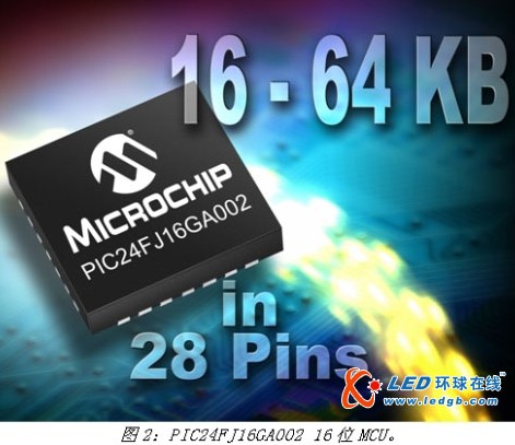
For color control systems, MCU devices such as the PIC24FJ16GA002 (see Figure 2) are a good choice. The PIC24 device is available in a small 28-pin package with a program memory range of 16 to 64 KB and provides a serial communication interface, 10-bit ADC, and 5 PWM channels in a single device. The 16-bit MCU core can easily handle arithmetic operations related to sensor calibration and color control.
The sensor data output must be calibrated against the reference voltage to provide consistent results. The calibration process uses a colorimeter to mathematically correlate the output of the different color LEDs with the spectral response and the sensitivity of the light sensor in a standard chromaticity coordinate system. The calibration process generates a matrix of coefficients that must be stored in the non-volatile memory with the illumination system and used to determine the difference between the associated and desired outputs in each control of the control system.
Once the calibration is complete, the MCU can compare the sensor data to the ideal CIE (International Commission on Illumination) chromaticity map coordinates and adjust the output channel until the desired CCT is obtained. The PID control algorithm for each output channel uses the calibration value to adjust the sensor data, find the difference from the target set point, and then adjust the output channel. In order to reduce the error, the PID will continue to run until the output CCT matches the set point CCT. The PID coefficient can be fine-tuned to maximize the system response, but the speed at which the PID algorithm converges to the target CCT is also a function of the efficiency of the MCU processing arithmetic operations. Some color control systems may require faster processing speeds and responsiveness than other systems. For example, general lighting systems require lower requirements than local dimming systems for HDTV panels.
Systems with adjustable light sources or high CRI have a range of user control requirements. Medical devices with a graphic LCD display may have an adjustable LED backlight (which requires the MCU to communicate with the LCD via SPI), as well as a touch screen interface for adjusting CCT and brightness. General lighting for commercial display devices may require control through a central panel or computer to automatically adjust brightness, CCT, and on/off according to each time of day. Communication between these devices can be done using hardwired serial bus protocols such as DALI or DMX512, while other devices may require a custom interface via USB or Ethernet. In a completed building, installing a hardwired infrastructure may not work and requires control via wireless communication and protocols such as ZigBee. For such lighting applications, MCUs with flexible peripherals are ideal for communication and user interfaces.
Light source technologies such as candles, kerosene lamps and incandescent lamps have replaced their previous technologies, thereby improving people's quality of life. The use of LEDs as a light source is just around the corner, and it is expected to enrich our lives better than all other light source technologies. LEDs have the advantages of high energy efficiency, small size, portability, durability and long life. Multi-color LEDs controlled by a small MCU can adjust the light output to provide comfortable illumination for the lighting space. The MCU intelligently controls the driver circuitry (which maximizes energy efficiency), monitors some conditions, and maximizes energy efficiency and average life. MCU color control LED lighting system will enable people to see the world with different eyes "light".
Engine drive Pump:
. Pump driven by diesel engine directly
. Pump driven by gas engine directly
. Water pump stantion
. Oil pump station
Engine Pump,Gas Engine Pump,Engine Driven Pump,Diesel Engine Pump
Guangdong Superwatt Power Equipment Co., Ltd , https://www.swtgenset.com