Abstract: Reversing radar is widely used in automobiles, but it is not connected with the car CAN bus network, resulting in imperfect functions. Design a reversing radar unit with PIC18F258 MCU, so that the reversing radar can be recognized by the vehicle planting network, realize data communication and resource sharing with the CAN bus, and complete the automatic braking function of the reversing radar.
Key words: CAN bus; reversing radar; PIC18F258; message
0 Introduction In the current automotive electronics field, the reversing radar generally adopts the principle of ultrasonic ranging, and calculates the distance between the obstacle and the vehicle through the single-chip microcomputer and displays and alarms. However, most of these products are independent control units that cannot be connected to the CAN bus, so they can only be used as a reversing safety aid. The PIC18F258 single-chip microcomputer is used to design a reversing radar unit to be connected with the on-board CAN network. This can transmit the measured distance information of the vehicle and obstacles to other control units on the vehicle CAN bus in the form of messages to achieve the necessary functions. When the distance between the vehicle and the obstacle is less than a certain value, the automatic braking function is realized by the braking unit to ensure the safety of the vehicle reversing; after the instrument control unit on the CAN bus receives the distance information of the vehicle and the obstacle, the distance can be displayed; After receiving the information on the CAN bus, the voice device can realize different frequency grading voice alarms according to the distance. In this way, the data sharing of the reversing radar unit on the CAN bus and its related units is realized, the function of the reversing radar is expanded, and the safety of the reversing is also improved.
1 CAN bus and vehicle CAN network communication
1.1 CAN bus CAN bus is a highly confidential field bus. It was developed by Bosch in Germany in the early 1980s to solve the data exchange between many control and test instruments in modern cars. A serial communication network that supports distributed control or real-time control. It has the following characteristics:
(1) The bus works in a multi-master mode, the system is flexible, the communication mode is flexible, and the unit information such as the address is not used;
(2) The unit information on the CAN bus network is divided into different priorities, which can meet different real-time requirements, and all information transmissions are sent in a fixed format;
(3) Using non-destructive bus arbitration technology, network congestion will not occur in the case of heavy network load;
(4) Only through message filtering, peer-to-peer, one-to-many, and global broadcasts can be used to receive and transmit data;
(5) The communication rate is inversely proportional to the distance. The direct communication can reach 10 km at a rate below 5 Kb/s, and the maximum communication rate can reach 1 Mb/s within 40 m.
(6) With error detection function, error notification function, error recovery function;
(7) The CAN bus unit will automatically turn off the output function in the event of a serious error, so that the operation of other units on the general route is not affected;
(8) The number of CAN bus units can theoretically be innumerable, but generally limited by the communication rate. The more units, the lower the communication rate, so the number of units is still limited.
1.2 On-board CAN network communication The main control units inside Hyundai Motor include: engine control unit, ABS control unit, airbag control unit, automatic transmission control unit, instrument management unit, window control unit, traction control unit, and fault diagnosis unit. , central control door lock unit, seat adjustment unit, lighting control unit, air conditioning control unit, rain control unit, rear view mirror control unit, etc. These control units form a real-time communication control network via the CAN bus, as shown in Figure 1.
This article refers to the address: http://
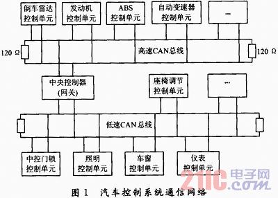
The control commands issued by the control units in the network must be responded promptly, reliably, and in a timely manner. Otherwise, it may cause the local control of the vehicle to fail, and in the event of a major accident of car crash. If all the control units of the whole vehicle are connected to a CAN bus network, all the control units communicate through a pair of CAN network lines. It is easy to have too many work points on the bus, the communication rate is reduced, and the system real-time response speed is reduced. The real-time response speed of critical control points will not be guaranteed. Therefore, after real-time analysis of each control unit on the vehicle, according to the different real-time requirements of each control unit, two high and low CAN communication networks with different rates are designed. The engine control unit with strict real-time requirements and high reliability requirements, the parking sensor control unit (design part of the subject), the ABS control unit, the automatic transmission control unit and the airbag control unit form a high-speed CAN communication network, and the real-time requirements are relatively The low central control door lock control unit, power seat adjustment unit, power window control unit, rear view mirror control unit, rain cover control unit and lighting control unit form a low-speed CAN communication network and configure a central controller ( The gateway connects the two CAN communication networks with different rates to achieve data sharing between all nodes. The high-speed CAN network has a transmission rate of 500 Kb/s, and the low-speed CAN network has a transmission rate of approximately 10 to 125 Kb/s. In Figure 1, the two ends of the bus should be connected to the 120 Ω termination matching resistor. If the termination resistor is not connected, the anti-interference and reliability of data communication will be greatly reduced, and even communication will not be possible.
2 reversing radar unit hardware design
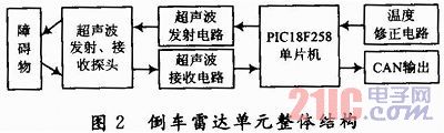
2.1 The overall design of the reversing radar unit The overall structure of the reversing radar unit is shown in Figure 2. In this design, the reversing radar uses the PIC18F258 MCU as the control core to control the ultrasonic transmitting and receiving circuits and the temperature correction circuit. The PIC18F258 microcontroller itself has a CAN bus, which reduces the complexity of the circuit. The ultrasonic transmitting circuit emits ultrasonic waves of 40 kHz. After the obstacle is reflected, the probe receives the reflected wave. The single chip calculates the distance between the obstacle and the vehicle according to the difference between the transmitting and receiving time, and sends the message to the meter unit through the CAN bus and displays it. It can also be sent to the audio unit for voice alarm. When the distance is less than a certain value, the corresponding brake unit will automatically brake. The temperature compensation circuit uses the digital temperature sensor DS18B20 to correct the sound speed by the relationship between the speed of sound and the temperature, thereby eliminating the influence of temperature changes on the sound.
PIC18F258 microcontroller has an advanced reduced instruction set architecture, enhanced core, 32-level stack and a variety of internal and external interrupt sources, with a CAN bus controller inside, and a "Harvard" structure with completely separate program and data space. The structure greatly reduces the overall cost while improving operational efficiency and reliability.
2.2 Reversing radar unit interface circuit design The hardware structure of the CAN unit generally has two forms. One form is a microcontroller with an internal integrated CAN controller plus a transceiver; another form is a general purpose microcontroller plus a separate CAN controller plus a transceiver. This design adopts the former form and does not occupy the port resources of the microcontroller, which simplifies the design of the interface circuit. Considering that the car works in a very special environment, Mierochip's PIC18F258 MCU, which meets the temperature range of the car and is cost-effective, has been selected. The chip integrates a CAN controller, which simplifies the hardware design of the system and improves the system. reliability. The reversing radar unit and CAN bus interface hardware circuit shown in Figure 3, mainly consists of PIC18F258 microcontroller, 6N137 high-speed optocoupler, PCA82 C250 bus transceiver three parts.
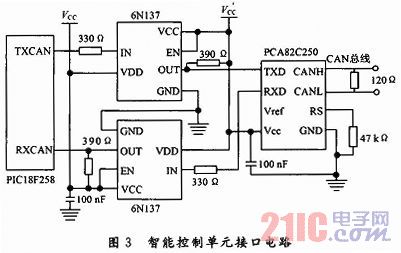
In order to improve the system's anti-interference ability and ability to transmit signals, the 6N137 high-speed optocoupler circuit can achieve good electrical isolation between the units on the bus. The two power supplies Vcc and V'cc of the high speed optocoupler must be completely isolated using a power isolation circuit.
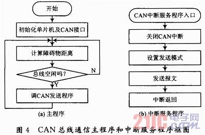
3 CAN bus communication software design CAN bus communication software design mainly includes CAN unit initialization, message transmission and message reception three parts. The initialization of the CAN interface is very important. If the design is not good, the system will not work properly. Initialization must first set the control register, status register, baud rate register, I/O control register, receive mask register in configuration mode. And several filter registers are set according to system requirements to ensure the smooth flow of the CAN bus.
The CAN bus communication main program and interrupt service program block diagram are shown in Figure 4.
4 Conclusion This paper uses PIC18F258 microcontroller to design a vehicle-based CAN bus reversing radar unit, making it an electrical unit of the vehicle CAN network. The overall structure of the reversing radar unit, CAN bus interface circuit and software design are given. The reversing radar unit main control chip PIC18F258 can send message data to other units through the CAN bus. Other controllers can realize related alarm, display, automatic braking and other functions through discrimination, which improves the safety of the car.
Taihang Power begin to produce rechargeable battery since 1956, our Nickel Cadmium Battery capacity range is from 10ah to 1200ah. NICD battery has the properties of rigid construction, long service life,wide work temperature, resistance to overcharge and overdischarge, low self-discharge, high reliability and easy maintenance.
They are widely used as DC power source for railway vehicle, rolling stocks, petrochemical, oil and gas, electricity industries,electrical appliance,telecommunications, UPS, military, AGV,electric power system,wind and solar energy storage system,etc.
Nickel Cadmium Alkaline Battery
Nickel Cadmium Rechargeable Battery,Nickel Cadmium Alkaline Battery,Alkaline Nicd Batteries,Nicd Battery For Ups
Henan Xintaihang Power Source Co.,Ltd , https://www.taihangbattery.com