1 Introduction
In today's society, with the development of the economy, people's living standards have improved, and more and more obese people have caused more and more diseases. Therefore, people are paying more and more attention to health problems, and exercising is to let The most effective way to be healthy. Therefore, the pedometer has emerged as the times require, and it has become a popular trend. When walking, by stretching the muscles, the blood's resistance during the flow decreases, and the blood pressure drops and stabilizes. People who walk often rarely suffer from high blood pressure or low blood pressure. Persistence in walking can reduce the fatty substances attached to the blood vessels, reduce weight, and gradually reduce the load on the heart. The pedometer based on the single chip microcomputer has the advantages of accuracy, reliability, stability and convenience, and has been accepted by most people. Through the pedometer, people can know how many steps they have run and master their exercise in real time.
2 overall design
The pedometer consists of an oscillating circuit, a reset circuit, a display circuit, and a button circuit, and is powered by a battery. The system structure diagram is shown in Figure 1.
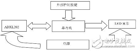
Figure 1 System structure diagram
3 hardware design
3.1 Oscillation circuit
The AT89C51 MCU has an oscillating circuit composed of an inverting amplifier. The oscillating circuit is a guarantee for the normal operation of the MCU system. If the oscillator does not vibrate, the system will not work. If the oscillator is running irregularly, the time error will occur when the system executes the program. This will be obvious in the communication, and the circuit will not be able to communicate.
It consists of a crystal and two ceramic capacitors. The two capacitors in the clock circuit are used as compensation, making the crystal easier to oscillate and the frequency more stable. as shown in picture 2.
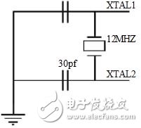
Figure 2 Oscillation circuit
3.2 reset circuit
In order to ensure stable and reliable operation of the circuit in the microcomputer system, the reset circuit is an indispensable part. The first function of the reset circuit is the power-on reset. Generally, the normal operation of the microcomputer circuit requires 5V ± 5% of the power supply, which is 4.75~5.25V. Since the microcomputer circuit is a sequential digital circuit, it needs a stable clock signal. Therefore, when the power supply is powered up, the reset signal is removed only when VCC exceeds 4.75V below 5.25V and the crystal oscillator operates stably. The microcomputer circuit starts normal. jobs. The reset of the system adopts the form of power-on reset. During the power-on process, the microcontroller reset pin ensures that the microcontroller is reset at a high level of more than 10ms. As shown in Figure 3.
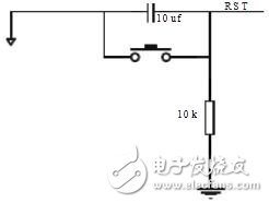
Figure 3 reset circuit
3.3 display circuit
This design uses a 4-digit LED common cathode digital tube display as the display interface of the system, as shown in Figure 4. The commonly used LED display is 8 or 7 segments (8 segments have a decimal point "dp" segment than 7 segments). Each segment corresponds to a light emitting diode. This type of display consists of a common anode and a common cathode. As shown in Figure 4. The cathodes of the LEDs of the common cathode LED display are connected together, usually sub-cathode grounded. When the anode of a certain LED is at a high level, the LED is lit and the corresponding segment is realized. In order for the LED display to display different symbols and numbers, it is necessary to illuminate the different segments of the LEDs, thus providing code for the LED display, because these codes can cause the corresponding segments of the LED to illuminate, thereby displaying different fonts, so The code is called a segment code (or a font code). The 7-segment LED is added with a decimal point for a total of 8 segments. Therefore, the segment code supplied to the LED display is exactly 1B.
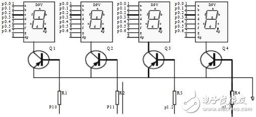
Figure 4 display connection circuit
3.4 button circuit
This design is to replace the vibration generated by the person walking in the form of a button. Each time the button is pressed, it means that the person walks one step. The circuit is shown in Figure 5.
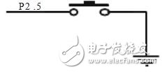
Figure 5 button circuit
3.5 ADXL202 Sensor Circuit
The ADXL022 sensor module circuit is shown in Figure 6.
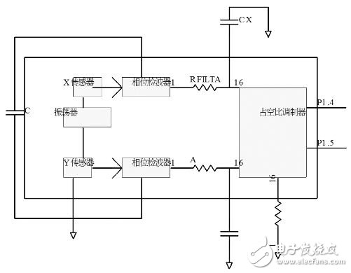
Figure 6 ADXL202 sensor module circuit
4 system software
The pace begins and the internal procedures are in place. When the person walks one step, the sensor detects the peak value, and after four kinds of circuits, it is displayed by the display, and then one step is taken, and the accumulator is incremented by one, thereby adding one step by step and displaying by the display. The microcontroller reset system generates an external interrupt and the display is set to zero. The system flow chart is shown in Figure 7.
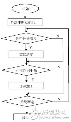
Figure 7 system flow chart
5 software simulation
In the system, the button K1 in the button circuit is connected with the P4.4 of the single chip microcomputer, and the dedicated button circuit generates an oscillating circuit, and the electric signal is converted to the microcontroller through the circuit, and the microcontroller will represent the digital quantity of the current step according to 10 After processing, it is displayed by visual LED. When the button is pressed once, the display shows 1, and how many times it is displayed. The pedometer simulation effect diagram is shown in Figure 8.
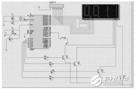
Figure 8 simulation renderings
6 Conclusion
The main design of this paper includes the microcontroller, display components, input components and real-time clock. In the entire design system, fully grasp the working principle of each module circuit, design the hardware circuit and software program, and finally simulate.
Laser crystals of various materials including Neodymium Doped Yttrium Aluminum Garnet (Nd:YAG), Yb-doped Yttrium Aluminum (Yb:YAG), Nd-doped Yttrium Orthovanadate ( Nd:YVO4 ), Nd-doped Gadolinium Orthovanadate ( Nd:GdVO4 ), Cr doped Yttrium Aluminum Garnet ( Cr4+:YAG ) and diffusion bonded composite crystal ( DBC crystal ) are available from Coupletech Co., Ltd.
Coupletech could supply many kinds of Laser Crystal with larger dimension, higher damage threshold, higher conversion efficiency and higher reliability for higher power Solid-state laser applications. We have strict quality control and continuous innovation. Coupletech's various finished laser rods, laser crystal, slabs and thin wafers as well as supplying laser crystal with brewster's angle, which is widely for use in industrial, medical and scientific applications.

S
Laser Crystal
Yb:YAG Crystals,Nd:YAG Crystals,Nd:YVO4 Crystals,Cr:YAG Crystals,Diffusion Bonded Crystals
Coupletech Co., Ltd. , https://www.coupletech.com