With the continuous advancement of processes and technologies, integrated circuit development has enabled the integration of a Programmable System on a Chip (SoC) onto a single chip. Among these, Field-Programmable Gate Arrays (FPGAs) have become widely used in the design of mathematical ASICs due to their flexible architecture and high-speed performance. The theory and implementation of Digital Signal Processing (DSP) have evolved rapidly and now stand as one of the fastest-growing disciplines globally. Thanks to its fast processing speed, powerful interface capabilities, and strong communication functions, DSP has found widespread application across various fields [1].
The MIL-STD-1553B data bus is characterized by bidirectional communication, real-time performance, and high reliability, making it a popular choice in modern transport aircraft, commercial airliners, and military aircraft.
**1. Composition of the 1553B Data Bus System**
The 1553B bus system is primarily composed of three key components: the Bus Controller (BC), the Remote Terminal (RT), and the Data Bus itself. The bus architecture of an aircraft is illustrated in Figure 1.
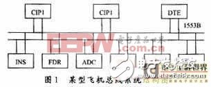
In this diagram, CIP1 represents the BC, while CIP2 serves as its backup. Other subsystems are RTs, and the bus system is designed with dual redundancy, where each set of buses acts as a backup for the other.
This article references the address: http://TIcle/241686.htm
CIP1 is a communication and information processing system, while CIP2 is its backup. DTE stands for Data Transmission Equipment, INS for Inertial Navigation System, FDR for Flight Data Recorder, ADC for Atmospheric Data Computer, IFU for Interface Unit, FCC for Flight Control Computer, SMS for System Management, and LRS for Laser Ranging System.
**2. 1553B Data Bus Communication Protocol**
The 1553B bus operates at a speed of 1 Mbps using Manchester II encoding in a half-duplex mode. The main hardware components include the Bus Controller (BC), the Remote Terminal (RT), and optionally the Bus Monitor (MT). These components are typically implemented through a Multi-Channel Bus Interface (MBI), which can be embedded within a computer. The bus supports ten message formats, with each message containing at least two words. Each word consists of 16 data bits, 1 parity bit, and a 3-bit length synchronization header. All words are encoded using Manchester II code. The word format used in the 1553B data bus is shown in Figure 2.

The 1553B data bus employs an instruction/response communication protocol, involving three types of terminals:
(1) **Bus Controller (BC)** – The only terminal responsible for initiating and controlling data transfers on the bus.
(2) **Remote Terminal (RT)** – Acts as the interface between the user subsystem and the bus, receiving or transmitting data under BC control.
(3) **Bus Monitor (MT)** – Monitors data transfer activity on the bus for recording and analysis but does not actively participate in communication.
**3. 1553B Data Bus Message Transmission Format**
Data on the 1553B bus is transmitted in messages, which consist of instruction words, data words, and status words. The following are the ten message formats defined by the 1553B protocol, as shown in Figure 3.

**4. Aircraft Bus System Communication Hierarchy**
Drawing from the ISO seven-layer model, the aircraft airborne system is structured into five layers: Application Layer, Driver Layer, Transport Layer, Data Link Layer, and Physical Layer, as illustrated in Figure 4.
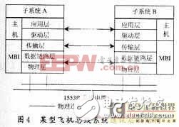
Each layer has clearly defined functions and simple interfaces, forming a solid foundation for hardware and software design [2]. The Application Layer manages communication system functions like initialization and data interpretation. The Driver Layer acts as a software interface between the Application Layer and lower layers, managing MBI operations. The Transport Layer controls data transmission, while the Data Link Layer ensures message sequence compliance with MIL-STD-1553B. The Physical Layer handles bitstream transmission on the physical medium.
**5. Bus System Communication Software Design**
Designing the communication software for an aircraft bus system is a critical task. It includes both the driver and application layers. The driver layer directly controls the bus interface board, configuring registers to enable data transmission and reception, while the application layer manages overall system functionality [3]. As an interface board, the focus is on the driver layer software, which includes three aspects:
(1) **FPGA-based software**
(2) **DSP-based software**
(3) **PC operating system driver software**
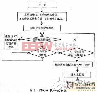
**5.1 FPGA Program Control Function**
This part is written in VHDL and handles 1553B data reception and transmission, Manchester II encoding, error detection, parity checking, and interfacing with the DSP and decoding circuits. The transmit and receive units operate in parallel, implemented via logic gates. A flowchart of the software is shown in Figure 5.
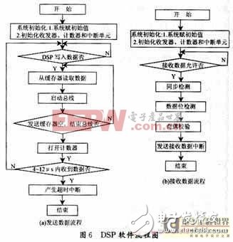
**5.2 DSP Program Control Function**
The DSP program performs several tasks, including initializing the bus interface board, recognizing RT addresses, controlling message transmission with the host computer, and handling interrupts. Key operations involve writing data to the FPGA, reading processed data, and performing self-tests. The interrupt control program uses three hardware interrupts generated by the FPGA and the host computer.
The DSP software combines C++ and assembly language, with critical paths implemented in assembly for maximum efficiency and the main program in C++. A flowchart of the DSP software is shown in Figure 6.
**5.3 PC Control Program**
This program is responsible for implementing the driver software, data communication, and transmission control of the interface board under a specific operating system. It is mainly developed in C++ for Windows environments.
**6. Conclusion**
This paper presents a method for designing and implementing communication software for an aircraft bus system based on FPGA and DSP technology. In practical applications, the communication function of the bus system was successfully realized, offering valuable reference for research on the 1553B bus.
Yuhai Company develop and produce of various hemisphere, electrode and metallisation configurations. This range is fabricated from various piezoelectric material formulations for applications such as high power, sensitivity, stability needs.
Features
- Choice of metallisation (Silver, Nickel, Gold and others on request)
- Thickness frequency tuning available on request
- Wide choice of PZT formulations
-
Applications include
- Sonar transducers
- Hydrophones
- HIFU medical and industrial
- Underwater communications
Dimension range
| Diameter | 6-160mm |
| Wall thickness | 1-10mm |
Piezo Ceramic ,Pzt Piezo Ceramics,Piezo Hemisphere,Pzt Piezoelectric Hemisphere
Zibo Yuhai Electronic Ceramic Co., Ltd. , https://www.yhpiezo.com