Note: This simulation focuses on the words "imitation" and "true." Integrating these two concepts requires careful attention to many details. This article highlights two critical points that can help improve accuracy in simulations.
Background Introduction
In high-speed digital design, the electrical path between a transmitter and a receiver is often referred to as the channel. Channel performance plays a crucial role in determining signal integrity. One common approach to evaluate this performance is through ADS (Advanced Design System), which allows for both electromagnetic (EM) and time-domain simulations.
Typically, the process involves using an EM simulator like ADS Momentum, SIPro, or EMPro to extract S-parameters of the channel. These S-parameters are then used in time-domain simulations, where eye diagrams are commonly analyzed to assess signal quality.
However, ensuring accurate results from time-domain simulations depends heavily on the precision of the extracted S-parameters. This document explores some of the key details that should be considered when working with S-parameters to maintain simulation accuracy.
Channel Time-Domain Simulation
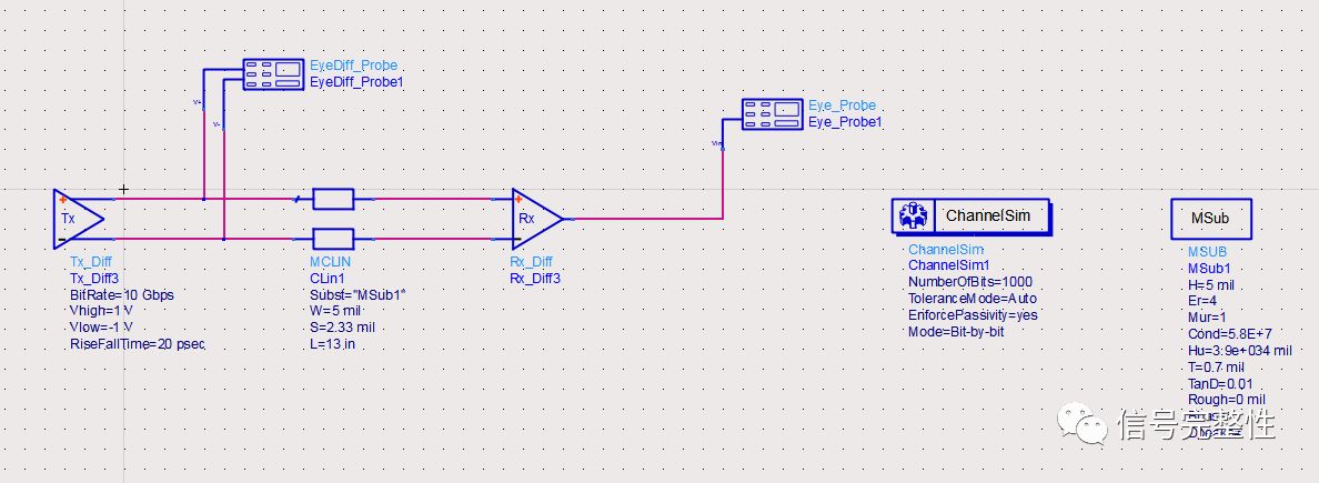
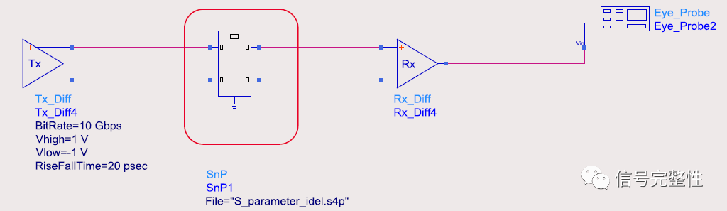
To illustrate this, let’s look at a specific example. The following circuit represents a simple differential channel, with ideal transmitter and receiver models connected by a pair of differential lines. The signal rate is 10 Gbps, with a rise and fall time of 20 ps.
The resulting eye diagram is shown below:
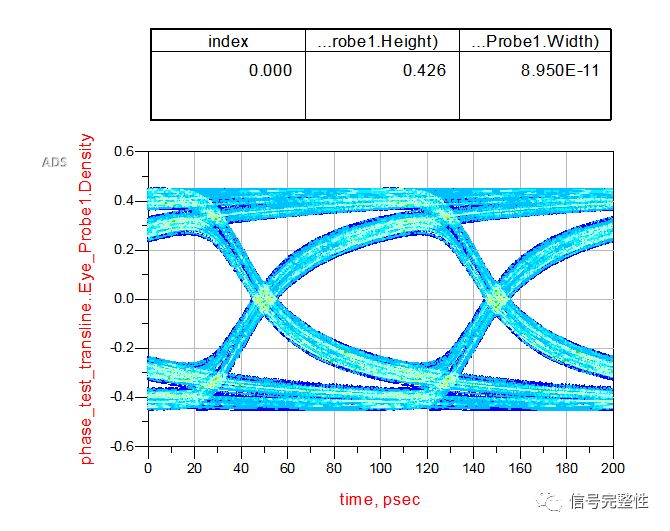
This eye diagram looks very good, with an eye width of 89.5 ps and an eye height of 426 mV. Next, we conducted an experiment to extract the S-parameters of the transmission line.
Extracting S-Parameters of the Transmission Line
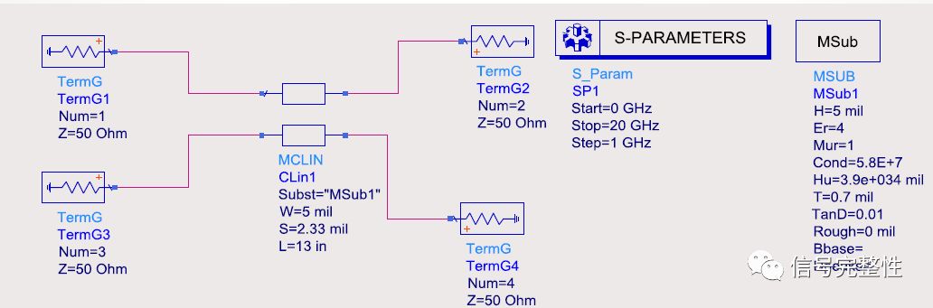
Using an S-parameter solver, we extracted the S-parameters of the differential line across a frequency range of 0–20 GHz, with a step size of 1 GHz.
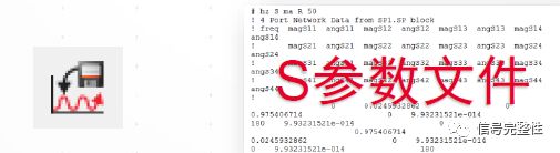
After the simulation, we converted the data into an S-parameter file using a data extraction tool.
We then replaced the original transmission line with the extracted S-parameters and performed another channel simulation. The circuit setup is shown below:
The resulting eye diagram was as follows:
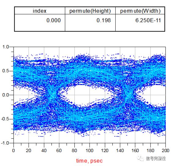
The eye width was 62.5 ps, and the eye height was 198 mV—clearly different from the original results. The eye margin had decreased significantly, and noise and jitter were much higher. To investigate further, we repeated the process with a smaller frequency step of 0.1 GHz.
With a 0.1 GHz step, the eye diagram improved dramatically:

The eye width increased to 93.5 ps, and the eye height reached 397 mV. Further reducing the step to 0.01 GHz led to even better results:

The eye width was 89.5 ps, and the eye height was 403 mV—very close to the original values. While finer steps improve accuracy, they also reduce simulation efficiency.
Next, we tested varying bandwidths while keeping the frequency step at 0.01 GHz. We extracted S-parameters at 15 GHz, 20 GHz, and 30 GHz and simulated each case. The results showed that increasing the bandwidth brought the simulation closer to the original performance.
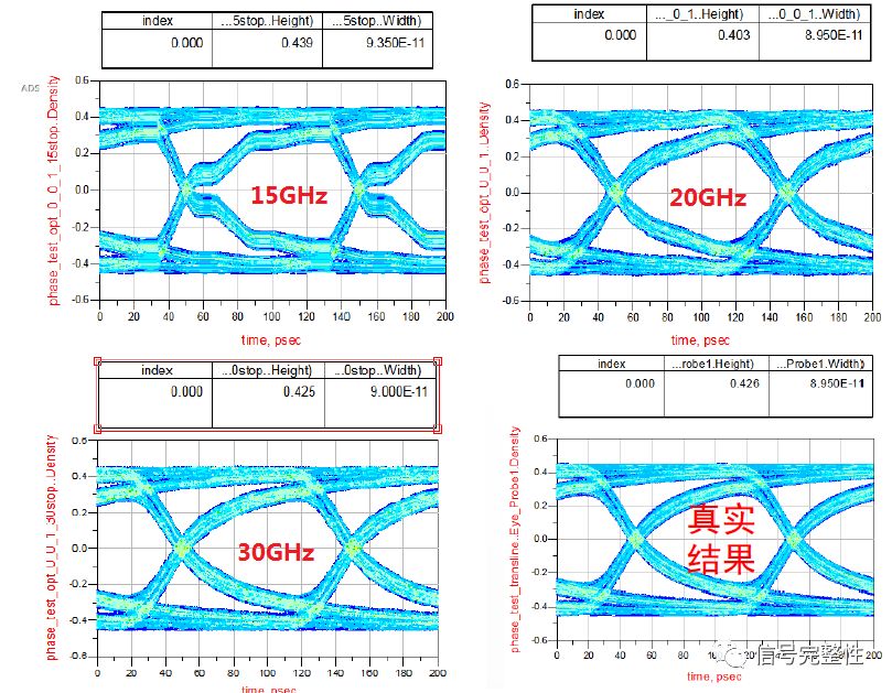
Here are the eye widths and heights for each simulation:
| Eye Width (ps) | Eye Height (mV) | |
| Original (10 GHz) | 89.5 | 426 |
| 15 GHz | 93.5 | 439 |
| 20 GHz | 89.5 | 103 |
| 30 GHz | 90 | 425 |
From the above results, it's clear that when the S-parameter bandwidth reaches three times the required signal bandwidth, the simulation becomes more accurate.
Conclusion
1. A smaller frequency step leads to more accurate S-parameter models, closer to the original results.
2. Increasing the bandwidth of the extracted S-parameters improves the model's accuracy.
3. For a 10 Gbps system, to closely match the original performance, it's recommended to use a 0.01 GHz frequency step and a 30 GHz bandwidth. Modern simulation tools can achieve this level of precision using internal interpolation or adaptive algorithms.
Catering to the ever-changing demands of our patrons, we are offering them a comprehensive range of Hot Dip Galvanized Radiator. These are manufactured as per latest market trends so as to ensure their wide applications in industries. Offered products are highly demanded by the clients for their excellent design, longer service life and durability.
Galvanizing is a way of defending a steel surface from corrosion by delivering a surface coat of Zinc. The process is carried out by dipping the radiator in molten zinc bath which is upheld at a temperature of about 450 degrees.
In long-term, continuous exposure, the recommended maximum temperature for hot-dip galvanized steel is 200 °C (392 °F), according to the American Galvanizers Association. The use of galvanized steel at temperatures above this will result in peeling of the zinc at the inter metallic layer.Hdg Radiator,Oil-Immersed Hdg Radiator,Hot-Dip Galvanizing Radiator,High-Performance Hot Dip Galvanized Radiator
Shenyang Tiantong Electricity Co., Ltd. , https://www.ttradiator.com