Abstract: With the implementation of national energy policies, power plants are increasingly adopting high-voltage inverters to drive motors. This paper introduces a newly developed inverter motor differential protection device by a leading technology company. The device employs the sampling value differential principle to provide accurate differential protection for inverter-driven motors. It integrates both transformer and motor protection functions into a single unit, enhancing system efficiency. A hard pressure plate, activated through a bypass switch, serves as a backup protection mechanism.
Keywords: motor protection; transformer protection; phasor differential; sampled value differential; bypass switch
In line with national energy policy requirements, energy conservation and emission reduction have become central priorities. In large thermal power plants, reducing the plant's own power consumption is essential. High-voltage motors, which consume the majority of the plant’s electricity, are a key target for energy-saving measures. One such measure is the application of high-voltage frequency conversion technology. As power electronics advance, frequency converters have become widely used in power plants. New auxiliary power plants now typically require frequency converter configurations for critical equipment like fans and pumps, while many existing plants are undergoing or have completed the retrofit of high-voltage motors with inverters. Ensuring reliable motor protection after inverter installation has become a major concern for power plants, design firms, and protection manufacturers alike.
Asynchronous motor faults typically include phase-to-phase short circuits, inter-turn short circuits, and single-phase ground faults. Abnormal operating conditions may involve overload, stalling, prolonged starting times, three-phase imbalance, or voltage anomalies. According to industry standards, high-voltage motors are primarily protected using differential or current quick-break protection. Additional backup protections include overcurrent, overload, negative-sequence, zero-sequence, and low-voltage protection. These measures ensure comprehensive safety and reliability.
To ensure the reliability of power generation systems, high-voltage motors often use frequency converters equipped with a power frequency bypass. This allows the motor to continue operating during inverter maintenance. Figure 1 illustrates the field configuration of a high-voltage inverter motor. Switches K1 and K2 isolate the main circuit during inspection, while K3 closes to route the motor through the bypass.
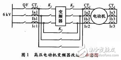
When running through the bypass, the motor is directly powered from the factory’s high-voltage busbar. At this point, the protection system at the incoming switch QF monitors the switch outlet and the motor itself. Therefore, motor protection must follow conventional settings. If differential protection is required, it should be configured accordingly.
However, when the bypass switch K3 is open and the motor is driven by the inverter, the protection object changes. The incoming switch QF now protects the switch outlet and the inverter. Since most power plant inverters include a rectifier transformer, the protection device at QF covers the transformer. At this stage, the motor becomes the load of the inverter and is isolated from the factory bus. Hence, motor protection is handled by the inverter’s control system. For 6–10 kV rectifier transformers, conventional transformer backup protection is usually implemented, though timing differences exist compared to standard transformers. Conventional motor differential protection is not applicable due to mismatched current frequencies between the switch and the motor’s neutral side, so it is typically disabled.
Current inverter motor protection setups generally include a motor protection measurement and control device, a motor differential protection device, and a transformer protection measurement and control device. These devices switch functions via the bypass switch: when the bypass is open, the inverter drives the motor, and the transformer protection is active while motor protection is disabled. When the bypass is closed, the motor runs on the power grid, and motor protection is enabled while transformer protection is disabled.
50W Medical Power Supply,Battery Backup For Medical Equipment,Medical Ac Adapter,Isolated Power Supply For Hospital
Shenzhen Longxc Power Supply Co., Ltd , https://www.longxcpower.com