Reading a power supply circuit diagram can be one of the most challenging tasks for beginners. Some diagrams contain dozens or even hundreds of components, making it difficult for many to understand them at first glance. However, with some experience and key strategies, you can quickly grasp the content of a power supply circuit. This article will guide you through the essential points of reading power supply circuit diagrams, along with practical examples.
A power supply circuit is a fundamental yet widely used type of electronic circuit. When you are given a power supply schematic, it's important to follow a structured approach to analyze and understand it. Here are the key steps:
1. Begin by breaking down the circuit in the order of “rectification, filtering, and stabilization.†Analyze each stage step by step to get a clear picture of how the circuit operates.
2. During this process, distinguish between the main circuit and auxiliary circuits, as well as primary and secondary components. Understand their functions and required parameters. For example, in a switching power supply, the inductor and freewheeling diode are critical components that determine performance.
3. Keep in mind that transistors come in NPN and PNP types, and some integrated circuits require dual power supplies. As a result, power supply circuits often have multiple voltage outputs with different values and polarities. When reading the diagram, make sure to identify the correct voltage levels and polarities for each output. Pay extra attention to transistor polarity and electrolytic capacitor orientation during assembly or repair to avoid mistakes.
4. Familiarize yourself with common drawing conventions and simplified representations used in power supply schematics. These techniques help reduce complexity and make the diagram more readable.
5. Finally, integrate all the parts from the beginning to the end of the circuit to fully understand the overall function of the power supply.
Examples
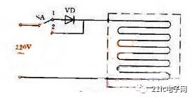
Figure 1: Electric Blanket Circuit
Figure 1 shows an electric blanket circuit. When the switch is set to position "1," 220 volts AC is connected to the heating element via a diode, resulting in half-wave rectification. This produces a pulsating DC voltage of approximately 100 volts, which provides low heat, suitable for keeping warm. When the switch is moved to position "2," the 220 volts AC is directly applied to the heating element, resulting in high heat output.
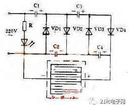
Figure 2: High-Voltage Mosquito Killer Circuit
This circuit uses a voltage doubler rectification principle to generate a high-voltage DC output. After four-stage rectification of 220 volts AC, the output voltage can reach up to 1100 volts. This high voltage is applied across a grid of parallel wires. A bait is placed underneath the grid, and when an insect lands on the wire, it creates a short circuit. The high voltage then discharges through the insect’s body, killing it. Once the insect falls, the capacitor recharges, restoring the high voltage. The current is very small, so the grid is safe for humans.
Since insects are attracted to light at night, placing a 3-watt fluorescent lamp or a black light behind the grid can effectively trap mosquitoes and other pests.
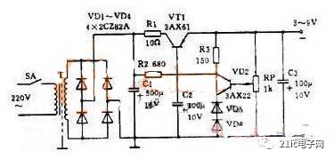
Figure 3: Practical Regulated Power Supply
Figure 3 illustrates a practical regulated power supply capable of delivering an adjustable output voltage ranging from 3 to 9 volts with a maximum current of 100 mA. This is a series-type regulator circuit. Key details to note include:
1. The rectifier bridge is drawn differently than in Figure 2(c), but it still represents a standard bridge rectifier configuration.
2. The circuit uses a PNP transistor, meaning the output voltage is negative, and the anode is grounded.
3. Instead of a Zener diode, two regular diodes are used. Since the forward voltage drop of a diode is relatively constant, they can replace a Zener diode. For example, two 2CZ diodes can be used to provide a stable reference voltage.
4. A potentiometer is used as the sampling resistor, allowing the output voltage to be easily adjusted.
In addition, any circuit that amplifies weak signals is known as an amplifier. In devices like hearing aids, the core component is the amplifier. By following a systematic approach—starting with the basic stages, analyzing each part in detail, and then connecting everything together—you can quickly understand even complex power supply circuits without confusion.
Dropout Fuse Cutout and load drop fuse cutout are outdoor used high-voltage protective devices. They are connected with the main lines of the distribution transformer or the distribution wires to protect the transformer or wires from short circuit and overload, and on/off loading current. Dropout fuse cutout consists of insulating bracket and fuse tube. The static contacts are fixed on the two ends of bracket, while the moving contacts are fixed on the two ends of fuse tube. Fuse tube is composed of inner extinction tube and the outer epoxy glass tube. The load drop fuse cutout is added with elastic supporting contacts and arcing shield for switching on-off loading current. In normal operation, the fuse tube will form an enclosure via its tightened fuse link. The fuse will be melt off quickly and form an arc if there is any fault, the extinction tube is heated by the arc, exploding much gas to give high pressure into the tube and blow along with the tube, so the arc is quickly elongated and extinguished. When the fuse is cut off, moving contacts at the bottom turn down without tension; the locking frame will release the fuse, so the fuse drops to form obvious break. When it needs to put load on, start the contact with insulating cod, then the static and moving contacts are still keeping in touch, keep pulling the contacts till the supporting contacts apart. Then there is the arc among the supporting contacts, which is prolonged in the narrow space of arcing shield.At the same time, the arc extinguishing cover generates gas, and the arc is extinguished when the current exceeds zero.
Porcelain Fuse Cutout,Drop Fuse Cutout,Fuse Link Cut Out,Cutout Fuse Holder
Jilin Nengxing Electrical Equipment Co. Ltd. , https://www.nengxingelectric.com