1 Introduction
The working characteristic of the traction machine brake is the electric suction and the electric brake. Therefore, when the elevator is running, the brake is in the energized suction state, which requires the brake to have sufficient electromagnetic suction to ensure the normal operation of the elevator, and The brake must also meet the other two conditions :1 When the voltage is reduced to 80% of the rated voltage, the brake can be reliably sucked; 2 In the pull-in state, when the voltage is reduced to 55% of the rated voltage, the brake can still have enough suction to release, this is The brakes must be required to meet the needs of different operating points. However, due to space and cost constraints, the brakes cannot be made very large. Therefore, it is particularly important to accurately calculate the electromagnetic parameters of the brakes.
2 Structural principle
Whether it is a block brake, a drum brake or a stacked brake, the electromagnetic structure is basically the same, as shown in Figure 1:
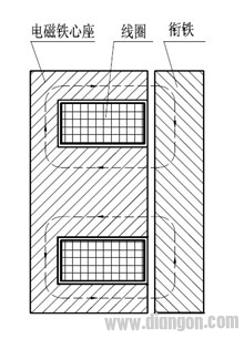
Figure 1 Schematic diagram of electromagnetic structure
The electromagnet core seat, coil and armature form the most basic electromagnetic structure of the brake. When the coil passes current, the electromagnet core will generate magnetic flux. If the leakage flux is not considered, the magnetic flux path will be from the bottom of the electromagnet core to the outside of the electromagnet core. The outer air gap of the electromagnet core seat→the armature→the inner air gap of the electromagnet core seat→the inner part of the electromagnet core seat forms a loop. Due to the existence of the magnetic flux between the air gaps, the electromagnet core seat generates a pulling force on the armature, and the armature moves to the iron core under the electromagnetic pulling force. The resulting electromagnetic pull can be calculated as follows:
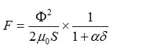
F—electromagnetic suction, the unit is N
—The magnetic flux flowing out of the air gap at the end of the electromagnet core, in Wb
00—air permeability coefficient, the value is
S—Electromagnetic core end face out of the magnetic ventilation gap area, the unit is
——correction factor, generally 3 to 5
Δ—air gap length, here the unit is cm
Through the above formula, the electromagnetic suction force can be easily calculated. However, the magnetic flux flowing out from the air gap of the electromagnet core end face needs to be obtained by the magnetic circuit calculation. Therefore, the design of the brake must be performed for the magnetic circuit design and calculation.
3 Magnetic circuit analysis and calculation
According to the electromagnetic structure diagram, it is convenient to draw the magnetic flux distribution state, as shown in Figure 2:
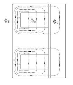
Figure 2 Magnetic flux distribution state diagram
It can be seen from Fig. 2 that the distribution of the leakage flux flows along the inner circular surface of the outer circumference of the electromagnet core facing the outer portion of the electromagnet core. Since the magnetic potential of each point is different, the height along the inner core of the electromagnet core is The distribution of magnetic flux is also different, and the distribution of magnetic flux leakage is obviously different. Therefore, the magnetic flux near the bottom of the electromagnet core is the most, close to the total magnetic flux. 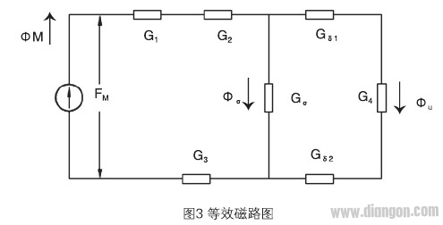 M, the magnetic flux near the top of the electromagnet core is the least, approximately equal to the effective flux u, but for the convenience of calculation,
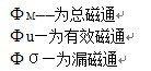
Here, an approximate equivalent magnetic circuit is introduced for calculation, as shown in Figure 3:
In the figure: G 1 - the magnetic permeability of the bottom of the electromagnet core; G 2 - the external magnetic conductance of the electromagnet core; G 3 - the internal magnetic conductance of the electromagnet core; G 4 - the armature magnetic conductance; G δ 1 - the outer air gap of the electromagnet core Permeance; G δ 2 — internal air gap permeability of the electromagnet core; G σ — leakage flux
Since G 2 and G 3 are soft magnetic materials, the values ​​are much larger than G δ 1 , G δ 2 , and G σ . Therefore, the error caused by this approximate equivalent magnetic circuit is relatively small, which can be said to be in engineering calculation. Within the allowable range, according to this approximate equivalent magnetic circuit, the following relationship can be listed :
The above relationship is solved:
Obviously, the magnetic flux leakage coefficient is related to the air gap magnetic conductances G δ 1 , G δ 2 and the armature magnetic conductance G 4 . Since the air gap magnetic permeability is much smaller than the armature magnetic permeability, the air gap magnetic permeability plays a decisive role in the magnetic flux leakage coefficient. Also, it approximates a constant.
4 electromagnetic design program
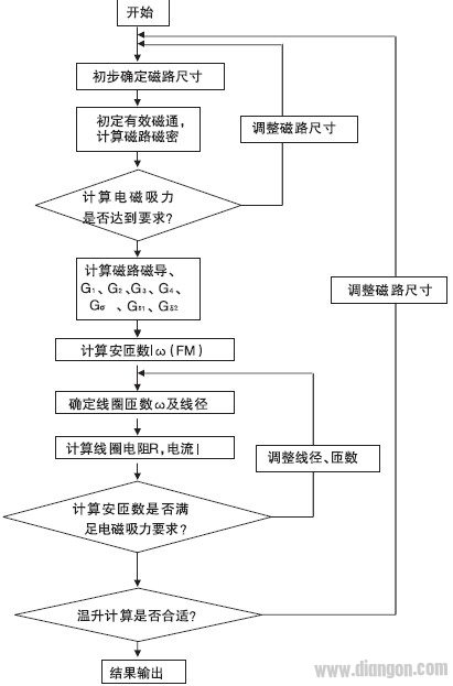
According to the rated data: working voltage U, working stroke δ, electromagnetic suction force F, insulation grade and other known conditions, for the electromagnetic suction force F is generally calculated according to the braking torque, brake wheel diameter, friction coefficient and other parameters of the electromagnetic suction force F, and insulation The grade defines the maximum allowable temperature rise. Based on these known conditions and the above relationship, the preliminary design and characteristic check can be performed, using the calculation program box shown in Figure 4.
Figure 4 calculation block diagram
After the iterations are calculated several times according to this calculation procedure, the electromagnetic parameters satisfying the electromagnetic attraction can be designed. However, it is necessary to pay attention to the design according to the rated voltage of 80% of the operating conditions, and then check whether the release requirements are met according to the 55% of the rated voltage. If the requirements are not met, the magnetic circuit size or coil needs to be adjusted. After the parameters are met, the electromagnetic design work is completed.
5 Conclusion
The test results of the prototype prove that the calculation method proposed in this paper and the approximate equivalent magnetic circuit calculation result are close to the actual one, and it is feasible as engineering application. The design method can be used not only for the traction machine brake, but also for the electromagnetic of other brakes. Design can also provide reference and reference for related electromagnetic design.
Dc Power Cables
- 2.1mm x 5.5mm DC Plug Extension Cord, Male to Female
- Cable - 3 ft, 20AWG, UL 2468 (UL Component)
- Connectors - Female: 2.1mm x 5.5mm jack. Male: 2.1mm x 5.5mm barrel plug. Spring locked tip for solid connection.
- For DC power - Recommended up to 36 volt, max load 3 amp or less
- This cable will only work with power Adapter with 2.1mm x 5.5mm plug and not other sizes.
Dc Power Cables,Dc Cable,Dc Power Cord,Ac Dc Power Cord
CHANGZHOU LESEN ELECTRONICS TECHNOLOGY CO.,LTD , https://www.china-lesencable.com