With the continuous development of analog technology, various simulators have been used in many fields of military and civilian use, and have played an important role in personnel training and prototype development, and have exerted significant economic and social benefits. In practice, since many sets of simulators are often developed for different models and equipments of the same series, resulting in high cost and low utilization of storage space. Developing a universal simulator for a specific field is a good idea to solve these problems. The necessity of the development of the universal simulator was analyzed from the aspects of equipment development, simulation training and personnel training, and the feasibility analysis was carried out. A universal search radar simulator and a satellite measurement and control universal simulator were designed.
In the design and development process of a general simulator for a certain type of ship electronic equipment, the author finds that the overall structure and appearance layout of the same series of different models are basically the same, the main difference is that the local operating components are different. In order to realize the generalization of the simulator, this paper designs and implements a multi-function rotary operation panel based on automatic control of stepping motor.
1 rotary operation panel hardware design
1.1 Composition
The rotary operation panel is composed of a component trihedron, a control board, a stepping motor assembly, a rotating body spindle, and a host computer. The control board sends a control command to the stepping motor assembly, and the stepping motor assembly drives the component trihedron to rotate the operation panel through the rotating body main shaft. The workflow is as follows:
(1) The host computer software issues a rotation switching command to the control board to send the step pulse signal and the direction level signal to the stepping motor component.
(2) After receiving the signal, the stepper motor assembly rotates the component trihedron to the appropriate position and ends the rotation operation.
(3) The user operates the components on the trihedron of the component, and the operation result is uploaded to the upper computer software, and the upper computer software performs corresponding processing.
1.2 component trihedron design
In a general simulator of a ship's electronic equipment, the component trihedron can realize three different types of interface layout structures (see Figure 1). The three faces of the component trihedron are denoted as A face, B face, and C face, respectively. The A surface component is five buttons; the B surface component is two indicator lights, one buzzer, one button and three knobs; the C surface component is four knobs.
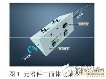
The component signal on the component trihedron is led to the control board through the data line, and communication with the host computer is realized. In order to avoid the entanglement of the data line during the rotation process, one of the operation surfaces is selected as the reference operation surface, and the other two surfaces are operated by the reciprocating two-way rotation reset mode.
1.3 control panel design
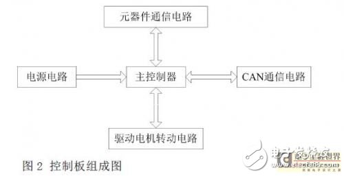
The rotary panel control board consists of a main controller, a power supply circuit, a CAN communication circuit, a drive motor rotation circuit, and a component communication circuit (see Figure 2). The main controller receives the host computer command and rotates the component trihedron to the appropriate plane position. The power supply circuit converts 12V to 5V, and then converts the 5V voltage to 3.3V for supply to the main controller. The CAN communication circuit is mainly composed of a CAN bus interface and a CAN transceiver, and is connected to the host computer and receives CAN communication commands. The driving motor rotating circuit mainly completes sending the stepping pulse signal and the direction level signal to the motor, and drives the motor to rotate, so that the component trihedron is rotated. The component communication circuit realizes the communication between the components and the host computer.
2 communication protocol design
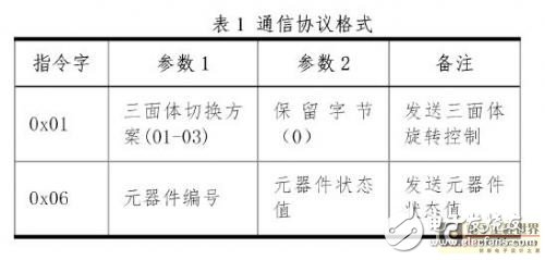
In order to realize the communication between the host computer software and the control board software, it is necessary to design a communication protocol format. Communication instructions are divided into two categories:
(1) The host computer sends a component trihedral switching command to the control board.
(2) The control board sends the component status command of the operation panel to the upper computer.
The communication protocol format is shown in Table 1.
3 software design
3.1 lower computer software design
The lower computer software mainly realizes the functions of receiving the instruction of the upper computer to drive the rotating component of the motor, the trihedron, and the operating state of the scanning component.
3.1.1 Receive command switching rotary panel
Determine whether the instruction is received, and when the instruction is received, go to Step2, otherwise continue to wait; set the step pulse signal and direction level signal; switch the panel to the appropriate position.
3.1.2 Scanning component status
Start the timer, periodically scan the component status; scan the component status to change, send it to the host computer program when the change occurs, otherwise continue to scan the component status periodically.
3.2 PC software design
The PC software adopts object-oriented technology, and the design focuses on the host computer communication class. The CAN communication interface uses a USB-CAN converter from Chime Electronics, which comes with a dynamic library that supports secondary development.
Using VC++ to realize the programming of the host computer communication class, the function of this class is mainly to issue the rotary operation panel switching scheme and receive component status. This class mainly includes a device initialization method (InitCan), a data transmission method (SendData), and a data receiving method (RecvData).
InitCan method
The InitCan method completes the connection and opens the CAN device. The input parameters are the CAN device number, the baud rate, and the output value is a Boolean type that identifies whether the CAN device is turned on.
Processing:
Load the send and receive instruction dynamic library; call the Init_can function in the dynamic library to connect and open the CAN device. SendData method SendData completes the issuing instruction function. The input parameter is the display instruction, and the output value is Boolean type, indicating whether the transmission is successful. Processing: Set the instruction to be sent; Call the Can_send function in the dynamic library to send the instruction. RecvData method RecvData completes the function of receiving and parsing instructions. Processing: Call the Can_receive function in the dynamic library to receive the instruction; parse according to the communication protocol, and conform to the protocol, otherwise it will not be processed.4 Conclusion
This paper designs and implements a multi-function rotary operation panel based on stepper motor automatic control, and is applied to the development of a general simulator for a certain type of ship electronic equipment, which better solves the simulation problem of the same series of different types of equipment operation panels. . The design scheme is also applicable to the design of other multifunctional electromechanical devices, and can provide a good reference for solving the problem of component layout when the available area of ​​the operation panel is insufficient.
Membrane switch is an operating system that integrates key functions, indicating elements and instrument panels. It consists of four parts: panel, upper circuit, isolation layer and lower circuit.
When the membrane switch is pressed, the contacts of the upper circuit are deformed downward, and are in contact with the pole plate of the lower circuit.
After the finger is released, the contacts of the upper circuit bounce back, the circuit is disconnected, and the circuit triggers a signal. The membrane switch has strict structure, beautiful appearance and good sealing performance. It has the characteristics of moisture resistance and long service life.
Widely used in electronic communication, electronic measuring instruments, industrial control, medical equipment, automobile industry, smart toys, household appliances and other fields.
Membrane Switch, Poly Membrane Switch, Home Appliance Membrane Switch, Membrane Switch with Leds, Membrane Switch Model
KEDA MEMBRANE TECHNOLOGY CO., LTD , https://www.kedamembrane.com