The use of frequency conversion technology to drive electric motors can achieve energy savings, in line with China's requirements for energy conservation and emission reduction and social needs. In order to apply the frequency conversion device to high voltage level and large capacity, high voltage and large capacity switching devices and multi-level topology are usually adopted; cascade type converter is a multi-level with good application prospect. Converters, cascaded inverters, such as cascaded high-voltage inverters, drag fans, pumps and other loads, most of which work in more important occasions, have a greater role in production or life, and have reliability requirements. High, generally requires the system to run continuously, even if the capacity is properly reduced after the failure, it can not be stopped at any time. In order to achieve the energy-saving goal by using a high-voltage inverter device to drive the motor, in order to ensure the reliability of the system, the high-voltage inverter device is required to have a certain fault-tolerant function, that is, when a device or a unit failure occurs, it can be automatically shielded, and the control method is adjusted. Keep the system running.
The unit series high-voltage frequency converter uses a plurality of low-voltage power units to realize high-voltage output in series. This structure makes it have good fault-tolerant performance; after the faulty unit is shielded, the system can continue to reduce the capacity operation through a certain fault handling method. Guarantee the stable operation of production. The traditional fault handling method is to shield the faulty unit from the corresponding non-faulty unit in the other two phases to maintain the balanced operation of the frequency converter, which will inevitably cause waste of the non-faulty unit, so the cascaded frequency converter works normally. Research on the processing method at the time of failure is necessary. The PCI9846-based inverter output performance test system designed in this paper mainly monitors and analyzes the indicators of the output power quality of the unit series high-voltage inverter when three different fault treatment methods are used, especially after the unit fails. The performance index of the system output voltage should be consistent with the fault before the fault to reduce the impact of the fault on the system work. The test system uses the LabVIEW virtual instrument software platform to build the system main control interface, and designs the corresponding fault handling method, which can obtain the reference wave for different fault handling methods. Tested on the simulation model of the multi-unit cascade inverter, the three-phase voltage signal is collected by the ADLINK PCI9846 digitizer, and then analyzed and processed to obtain the amplitude, frequency, total harmonic content, and three-phase voltage phase of the three-phase line voltage. And other major performance indicators to check the output of the control algorithm during normal system operation and faulty operation.
Structure and working principle of a unit series high voltage inverter
The unit series high-voltage inverter adopts several low-voltage power units in series to realize direct high-voltage output. The structure is shown in Figure 1. The transformer used is a multi-isolated transformer, the primary side inputs high voltage, and the secondary side outputs are isolated from each other. , each power unit is supplied, that is, each H-bridge in the figure, and the three-phase structure of the system is similar. Each power unit is a three-phase input, single-phase output AC-DC-AC inverter with a unified structure. The structure of the power unit is shown in Figure 2.
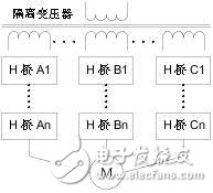
Figure 1 Unit series inverter structure
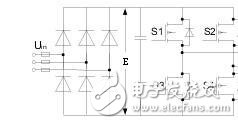
Figure 2 Power unit structure
Each power unit is powered by a set of secondary windings of the input transformer, and the power units are insulated from each other between the secondary windings of the transformer. If six phases are connected in series per phase, each power unit is subjected to the full output current, but only withstands 1/6 of the output phase voltage and 1/18 of the output power; for the 6KV motor system, the output voltage per cell is 0. ~590V adjustable, frequency 0~50Hz adjustable, which can realize frequency conversion control.
The power units of the unit series high-voltage inverters are controlled by carrier phase-shift PWM technology. For the inverter shown in Fig. 1, the reference wave voltage is modulated by n pairs of triangular carriers sequentially shifted by 60°/n. For the n signals obtained by the fundamental wave modulation of the A phase, A1 to An n power cells are respectively controlled, and a phase voltage waveform having a step of 2*n+1 steps is obtained by superposition. It is equivalent to 6*n pulse frequency conversion. In theory, harmonics below 6*n-1 times can be offset, and the total voltage and current distortion can be as low as 1%, so it is also called perfect harmonicless inverter. The power units of the same phase of the inverter output the same fundamental voltage, and the carriers between the series units are staggered by a certain phase. If the IGBT switching frequency of each power unit is 1 kHz, then there are 6 power units connected in series for each phase. The equivalent output phase voltage switching frequency is 12KHz. The power unit uses a low switching frequency to reduce switching losses, while the high equivalent output switching frequency and multi-level can greatly improve the output waveform. In addition to reducing output harmonics, waveform improvement reduces noise, du/dt values, and motor torque ripple. Therefore, the frequency converter is used for the speed regulating power supply and has no special requirements for the motor. It can be used for ordinary high-voltage motors without derating, and there is no special limitation on the length of the output cable.
Analysis of fault handling method for two-unit series high-voltage frequency converter
In order to improve the reliability of the unit series inverter, it can continue to operate after some power units fail. The traditional fault treatment method is to shield the fault unit and the corresponding non-fault unit in the other two phases to maintain the frequency conversion. The balanced operation of the device will inevitably result in waste of non-faulty units and thus a lower maximum output capability. The advantage of this method is that the principle is simple and the technology is mature and reliable.
In order to fully utilize all non-faulty units after a unit failure and further improve the output performance of the multilevel inverter, a neutral point shift technique can be employed. The principle of neutral shift is to make use of the neutral point of the inverter is floating, and is not connected to the midpoint of the load (such as the currently widely used three-phase motor), so the neutral point of the inverter can deviate from the midpoint of the load. Although the inverter output three-phase voltage is unbalanced, the three-phase balanced load line voltage can be obtained by adjusting the phase of the phase voltage. Such an adjustment method is equivalent to superimposing a zero sequence component on the asymmetric voltage outputted by the remaining units of each phase after the fault to synthesize a three-phase symmetrical line voltage. Since the two midpoints are not directly connected, the line voltage can generate a symmetrical load phase voltage on the load, thereby ensuring symmetric and stable operation of the load. However, since the three phases are no longer symmetrical, the optimal control method for increasing the cell voltage utilization by injecting the third harmonic is no longer applicable. Therefore, the neutral point shift processing method does not fully utilize the maximum output capability of the system. In some fault conditions, the maximum output capability is even lower than that of the conventional shielded faulty unit and its corresponding two-phase non-faulty unit.
In response to this problem, the literature [2] proposed a simple reference waveform generation method, which uses this reference waveform instead of sine wave for inverter unit control, which can be fully utilized without changing the original fault handling mode. The output capability of each unit increases the overall output of the system and reduces the impact of the fault on the load. This method is simple and easy. For the carrier-based control system, it is only necessary to change the shape of the reference wave according to the type of fault, and it can be realized without making major changes on the basis of the existing fault handling mode. There is no need to calculate the offset angle compared to the neutral offset method.
Taking the six-element cascade system as an example, when one unit of phase A fails, the principle and output of the three fault handling methods are compared as shown in Fig. 3.
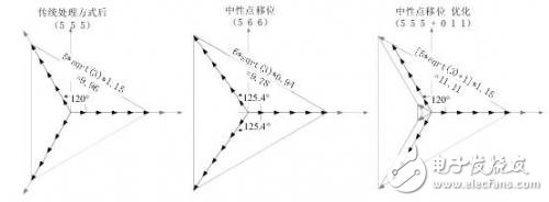
Figure 3 Comparison of three fault handling methods
Three test system design based on LabVIEW and PCI 9846
In order to verify the output performance of the above three fault handling methods of the cascaded inverter, the test system was built using the LabVIEW virtual instrument software platform and the ADLINK PCI 9846 high-speed digitizer. LabVIEW uses graphical system design concepts and unique parallel data flow features to provide significant advantages in master interface setup, fault handling method design, signal acquisition and processing, and voltage signal performance analysis. Since the equivalent output phase voltage switching frequency of the cascade type inverter is several times of the switching frequency of each switching device, the output voltage harmonics are distributed in a higher frequency band, so the sampling rate requirement of the data output device of the inverter output characteristic analysis system is required. Higher, common data acquisition devices are difficult to meet such high sampling requirements. ADLINK's modular instrument PCI 9846 has the advantages of high sampling rate, high sampling accuracy and good compatibility. The device has a maximum sampling frequency of 40MHz and four high-linearity 16-bit high-precision A/D. Simultaneous sampling of four channels has great advantages in the acquisition of high-frequency signals, and is very suitable for the acquisition and processing of high-frequency signals of three-phase output of cascaded inverters. ADLINK also provides drivers for LabVIEW that eliminate the need for excessive compatibility issues and reduce system development time.
The block diagram of the output characteristic test system of the cascaded inverter based on LabVIEW virtual instrument software platform and ADLINK PCI 9846 digitizer is shown in Figure 4.

Figure 4 Test system block diagram
Among them, the LabVIEW virtual instrument software is programmed in the PC, and according to the working principle of the above three fault handling modes, the corresponding control scheme is realized, and corresponding control signals are generated. The generated switching device control signal is outputted by the data output device, processed by the signal conditioning circuit, and sent to the cascaded frequency converter experimental device to operate the device. The output voltage is sent to the PCI 9846 via the sensor, and then the data is acquired at high speed and saved by an acquisition program written in LabVIEW. Then, the analysis software written by LabVIEW is used to process the saved signals, and the function of detecting and analyzing the output characteristics of the cascaded inverter is completed.
Four signal acquisition and processing results
The test system uses the LabVIEW virtual instrument software platform to build the main control interface as shown in Figure 5. Here, the six-unit cascade system is taken as an example for analysis, and the corresponding fault handling methods are designed respectively. When different fault handling methods are obtained through program design. Reference wave. Here, only the phase voltage equivalent to the reference wave and the obtained equivalent line voltage waveform are analyzed.
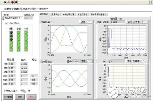
Figure 5 test system master control interface
In the above demonstration program, you can choose three different troubleshooting methods, the principle of which is briefly introduced in the corresponding tab label. The indicator light on the left is used to indicate the running status of each unit of the six-unit cascade system. The unlit indicator light indicates that the unit corresponds to a fault and is shielded. Figure 5 shows the operation of the three phases of the A phase. The indicator light has the output capability of the system at this time. It can be seen that in the case of three A phase failures, the partial zero sequence voltage is injected. By optimizing the adjustment mode, the system can still have an output capacity close to 75%, which is much better than the output capability of the traditional fault handling method (50% at this time). The area under the indicator light is the phase voltage, the normalized output of the line voltage rms, the total harmonic distortion of each phase voltage, and the phase of the three-phase line voltage. The tabs on the right side give the output waveforms of the three-phase phase voltage and line voltage and the harmonic analysis of one of the phases. In addition, the program also provides a zero-sequence voltage injection method to improve the utilization of the DC-side voltage, thereby improving the output capability of the system. It can be seen from the running result that after adopting this kind of fault processing mode, only the faulty power unit is shielded, so the three-phase phase voltage is no longer symmetrical, and the amplitude and phase are adjusted according to the fault type, and the obtained line is obtained. The voltage is still an equal amplitude, three phase balanced output and does not contain a third harmonic component.
Using the above program, the output of various faults is compared and analyzed, and the output performance is shown in the following table. The fault type indicates the number of normal units remaining in the three phases. For example, (466) indicates that the number of units in the three-unit cascade system is three in phase A, six in phase B, six in phase C, and total fault unit. The number is 2. At this time, the maximum output capacities of the three processing methods are 66.70%, 76.30%, and 83.40%, respectively. It can be seen that the maximum system output can be obtained by using the optimized midpoint shift, that is, the fault processing method of partial zero sequence voltage injection. When other fault types are used, the system output performance is also not lower than the first two processing methods.
Five conclusions
For the control problem of cascaded inverter unit failure, this paper compares and analyzes the existing three insufficiency treatment methods, and builds a six-element cascade inverter using LabVIEW virtual instrument software platform and ADLINK PCI 9846 digitizer. The output characteristic test system of the device has been tested and analyzed for three fault treatment methods, and the main performance indexes such as the amplitude, frequency, total harmonic content and three-phase voltage phase of the three-phase line voltage are obtained. By comparison, it is found that the fault processing method using optimized midpoint shift, that is, partial zero sequence voltage injection, can obtain the maximum system output after the fault unit is shielded, and improve the fault tolerance performance of the system. It is an ideal cascade inverter. Troubleshooting method.
Fork Type Connecting Terminals
Fork Type Connecting Terminals,Terminals,Connecting Terminals
Taixing Longyi Terminals Co.,Ltd. , https://www.txlyterminals.com