The structure and operation process of a four-axis linkage simple manipulator The structure of the manipulator is shown in Figure 1 below. It consists of a pneumatic control manipulator (1), an XY axis screw group (2), a turntable mechanism (3), a rotating base (4), etc. .
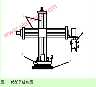
The motion control method is as follows: (1) the pneumatic control manipulator driven by a servo motor with a rotation angle of 360 ° (the photoelectric sensor determines the starting 0 point); (2) the stepper motor drives the screw assembly to make the manipulator move along X, Y-axis movement (with x and y-axis limit switches); (3) The turntable mechanism capable of rotating 360 ° can drive the manipulator and the screw group to rotate freely (its electric drag part is composed of DC motor, photoelectric encoder, proximity switch, etc. (Composition); (4) The rotating base mainly supports the above 3 parts; (5) The opening and closing of the air control manipulator is controlled by air pressure (the manipulator grasps when inflating, and the manipulator releases when deflating).
The working process is as follows: when the goods arrive, the manipulator system starts to move; the stepper motor controls the downward movement, while the other stepper motor controls the horizontal axis to start the forward movement; the servo motor drives the manipulator to rotate to reach the position where the goods are just grabbed And then inflate, and the robot grips the cargo.
The stepper motor drives the vertical axis to rise, and the other stepper motor drives the horizontal axis to start moving forward; the turntable DC motor rotates to move the manipulator as a whole and turn to the cargo receiving place; the stepper motor drives the vertical axis to descend again, and after reaching the specified position, The air valve is deflated, and the manipulator releases the cargo; the system returns to position ready for the next action.
Two control device selection
In order to achieve precise control, according to market conditions, the selection of various key devices is as follows:
1. Stepper motor and its driver
The longitudinal axis (Y axis) and horizontal axis (X axis) of the manipulator are 42BYG250C type two-phase hybrid stepper motors from Beijing Stone Motor Technology Co., Ltd., with a step angle of 0.9 ° / 1.8 ° and a current of 1.5A. M1 is a horizontal axis motor that drives the manipulator mechanism to extend and contract; M2 is a vertical axis motor that drives the manipulator mechanism to rise and fall. The selected stepper motor driver is the SH-20403 type. The driver uses 10 to 40V DC power supply, H-bridge bipolar constant-phase current drive, 8 output currents with a maximum of 3A are optional, and 7 subdivisions with a maximum of 64 subdivisions Optional mode, photoelectric isolation of input signal, standard single pulse interface, offline hold function, semi-closed cabinet can adapt to more severe working conditions, and provide energy-saving automatic half-current mode. The design of the switching power supply inside the driver ensures that the driver can adapt to a wider voltage range. The user can choose between 10 and 40 VDC according to their respective circumstances. Generally speaking, a higher rated power supply voltage is helpful to increase the high-speed torque of the motor, but it will increase the loss and temperature rise of the driver. The maximum output current value of this driver is 3A / phase (peak value), and 8 states can be combined through the 5th, 6th, and 7th digits of the 6-bit DIP switch on the driver panel, corresponding to 8 kinds of output currents, from 0.9A to 3A For use with different motors. This driver can provide 7 operation modes of full step, half step, 4 subdivision, 8 subdivision, 16 subdivision, 32 subdivision and 64 subdivision. 3 three bits can be combined into different states.
2. Servo motor and its driver
The rotation of the manipulator adopts Panasonic servo motor A series small inertia MSMA5AZA1G, its rated output is 50W, 100 / 200V common, the rotary encoder specification is incremental (pulse number 2500p / r, resolution 10000p / r, lead wire 11 lines) ; With oil seal, without brake, the shaft adopts keyway connection. The motor adopts Panasonic's unique algorithm to increase the speed frequency response by 2 times to 500Hz; the positioning over-adjustment time is shortened to 1/4 of the previous Panasonic servo motor product V series. With resonance suppression function, control function, and full-closed-loop control function, it can make up for the lack of mechanical rigidity, thereby achieving high-speed positioning, and can also be connected to a high-precision grating ruler to form a full-closed-loop control to further improve system accuracy. With conventional automatic gain adjustment and real-time automatic increase
There are two automatic gain adjustment methods, and RS-485 and RS-232C communication ports are also provided, so that the host controller can control up to 16 axes simultaneously. Servo motor driver is A series MSDA5A3A1A, suitable for small inertia motor.
3. DC motor
The turntable mechanism that can rotate 360 ​​° is driven by a DC brushless motor. The system uses a 57BL1010H1 brushless DC motor produced by Beijing Heshili Company. Its wide speed range, large low-speed torque, smooth operation, low noise and high efficiency. The brushless DC motor driver uses the BL-0408 driver produced by Beijing Heshili Company, which uses 24 to 48V DC power supply, has start-stop and steering control, overcurrent, overvoltage and stall protection, and has a fault alarm output, external Features such as analog speed regulation and rapid braking stop.
4. Rotary encoder
The E6A2 incremental rotary encoder produced by OMRON is installed on the turntable mechanism that can be rotated 360 °. The encoder transmits the signal to the PLC to achieve precise positioning of the turntable mechanism.
5. PLC selection
According to the design requirements of the system, the CPM2A minicomputer produced by OMRON is selected. CPM2A integrates various performances in a compact unit, including synchronous pulse control, interrupt input, pulse output, analog setting and clock function. CPM2A's CPU unit is an independent unit that can handle a wide range of mechanical control applications, so it is an ideal product for use as a built-in control unit in the device. The complete communication function ensures communication with personal computers, other OMRON PCs and OMRON programmable terminals. These communication capabilities make it easy to integrate the four-axis linkage simple manipulator into the industrial control system.
Three software programming
1. Software flow chart
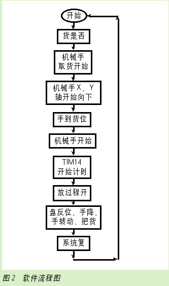
Flow chart is the basis of PLC programming. Only by designing a flow chart can it be possible to write a ladder diagram and a statement list smoothly and conveniently, and finally complete the design of the program. Therefore, it is very critical to write a flow chart and it is also the first task of program design. According to the control requirements of the four-axis linkage simple manipulator, the drawing flow chart is shown in Figure 2.
2. Program part
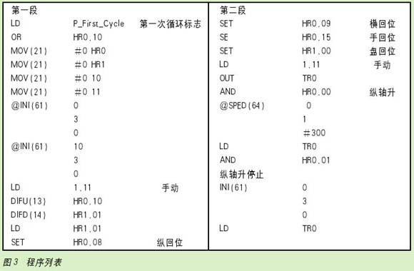
Due to the limited space of the paper, only the first two paragraphs of the program are listed here for readers to refer to, see Figure 3.
Four conclusions
The various actions and states of the four-axis linkage simple manipulator are controlled by PLC, which can not only meet the requirements of a large number of buttons, switches, and position detection points required for manual, semi-automatic, and automatic operation modes of the manipulator, but also can The computer forms a PLC industrial local area network to realize network communication and network control. The four-axis linkage simple manipulator can be easily embedded in the industrial production line.
funcTIon ImgZoom (Id) // Re-set the image size to prevent the form from being broken {var w = $ (Id) .width; var m = 650; if (w <m) {return;} else {var h = $ (Id) .height; $ (Id) .height = parseInt (h * m / w); $ (Id) .width = m;}} window.onload = funcTIon () {var Imgs = $ ("content"). getElementsByTagName ( "img"); var i = 0; for (; iPrinter Head And Interior Cleaning Kits
54X86Mm Cleaning Card,Cr80 Ipa Cleaning Card,Cr80 Adhesive Cleaning Card,54X86Mm Cr80 Cleaning Card
Miraclean Technology Co., Ltd. , https://www.mrccleanroom.com