Compared with current automotive interior and exterior lighting solutions, LED lighting has many advantages, such as higher performance, longer life, lower cost, etc. This lighting method also improves the aesthetics and performance of automotive lighting. However, if you want to directly drive an LED with a car battery, you need a DC / DC converter to regulate a constant LED current and protect the LED from the dramatic changes in the car battery. This converter should be optimized according to the number of LEDs in the series LED and the type of LED, and according to the function of the application such as headlights, taillights and signal lights, in-car reading lights, dashboard or entertainment display lighting, Please note:
1. Architecture —The relationship between LED voltage and battery voltage determines the use of buck, boost, or buck-boost architecture. The selected architecture should be able to maintain control of the LED current over the entire battery voltage range.
2. Dimming -A large proportion of LED dimming must maintain the same color characteristics at the brightness level, and there is no fluctuation or oscillation visible to the naked eye.
3. Efficiency -power consumption consumes battery power in the non-operational state, and in an environment where the heat pressure of the car is already large, the consumed power is converted into heat.
Drive a single LED
The white light headlights and makeup lights in the car may use one or two 3W LEDs, each of which produces a brightness of 75 to 100 lumens. The typical forward voltage range of these LEDs is 3V to 4.5V, and the maximum current is 1A to 1.5A, such as Luxeon III Star of Lumileds. The simplest LED driver design uses a buck regulator, which directly drives a single LED with a car battery.
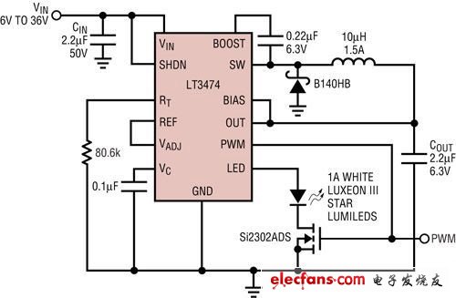
Figure 1: Step-down high-voltage 1A LED driver LT3474 with 250: 1 PWM dimming ratio.
As shown in Figure 1, it is a single LED internal lighting circuit with dimming function. The typical operating voltage range for automotive batteries is 9V to 16V (typical value is 12V). The voltage of a battery that consumes electricity may drop to 9V before the car is started. After the car starts, the alternator charges it to restore its voltage to as high as 14.4V. During a cold start, the battery voltage may drop to 4V. Only critical electronic circuits must work.
On the battery and the chassis, the long cables between different locations and the electronic noise environment make high voltage spikes always exist in the car. When choosing a switching regulator for automotive design, 36V transients must be considered, and usually higher voltage spikes are handled by simple protection diodes or filters. The integrated circuit of the LT3471 converter used in Figure 1 is a high-voltage, high-current step-down LED converter. This device has a wide PWM dimming ratio and can drive one or more LED currents up to 1A. The LT3471 provides a wide input voltage range of 4V to 36V, allowing the LED driver to operate directly from a car battery while providing constant LED current, while its buck architecture and adjustable wide frequency range allow the use of small, low cost, high temperature Coefficient ceramic capacitors provide low ripple LED current.
The efficiency of the LT3474 single LED buck converter is higher than 80% at 12VIN. When performing analog control through the VADJ pin, as the LED current and brightness decrease, the efficiency will decrease, but the power consumption will remain very low. The LT3474 is specifically tailored for automotive and battery-powered applications, and consumes less than 2uA (typically 10nA) of current when turned off. When it is turned off, the LED on / off button function can still be provided, just like the function of a button or a microcontroller. The LT3475 LED driver is a dual-channel version of the LT3474 that can drive two sets of individual LEDs or multiple strings of LEDs with a current of 1.5A each.
PWM dimming and brightness control
LED brightness can be controlled by the LT3474 in Figure 1, which connects an analog voltage input to the VADJ pin, or sends a digital PWM signal to the gate and PWM pin of the PWM dimming MOSFET. Simple analog brightness control reduces the constant LED current from 1A to a lower value by lowering the voltage of the internal sensing resistor, but the color of the LED light will change at low current. The practical limit of dimming ratio is about 10: 1.
Another way to reduce brightness is digital PWM dimming. During the PWM turn-on period, the LED current is maintained at a stable 1A. During the PWM off period, the LED current is zero. This reduces the brightness while maintaining the LED light color and true color characteristics.
Inside the integrated circuit, the PWM function allows the LED to return to the set current value to achieve a quick response to PWM dimming. The maximum digital PWM dimming ratio of the LT3474 is 250: 1, which is more than enough for internal lighting. The LT3475 can be dimmed with a dimming ratio higher than 1000: 1.
LCD display illuminated with multiple strings of LEDs
GPS navigation and in-car entertainment displays require bright series LEDs in daylight conditions and wide dimming ratios when working at night. Series LEDs pose different problems than single LED headlights. In these displays, as far as the smaller LEDs are concerned, multiple strings of LEDs consisting of 6 to 10 LEDs usually have a lower series current (<150mA), but the accumulated voltage is higher than the car battery voltage. For these displays In general, a high-power boost LED driver with high efficiency and PWM dimming capability is necessary.
Figure 2 shows the application of the LT3486 dual output boost LED driver, which drives two strings of LEDs with a constant current of 100mA, and the LED voltage is up to 36V. This boost converter has a small voltage sensing resistor in series with the LED and the PWM dimming MOSFET in series, and has high efficiency. The entire battery voltage range of 9V to 16V is lower than the voltage of the LED in series. The dual-channel LED driver drives two LEDs consisting of 20 LEDs in series while keeping the maximum switching voltage below the 42V rating of the integrated circuit. A single string of LEDs consisting of 20 LEDs in series requires a higher voltage.
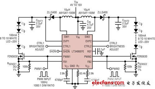
Figure 2: In a GPS LCD display, the LT3486 drives 20 white LEDs at 100mA.
We supply variety of output lead wire for motor and motor wiring harness. With the properties of chemical erode resistance, excellent bendability in high and low temperature environment and impregnating varnish erode resistance even at 302°F (150°C), this kind of wire also can bear high temperature of 392°F (200°C) with FEP and silicone rubber insulations. All of our wires and cables are UL, RoHS and REACH complaint such as UL1430, UL3266, UL3122 and UL1332 etc.
Motor Wire
Motor Wire,Single Phase Motor Wiring,Dc Motor Wiring,Motor Lead Wire
Feyvan Electronics Technology Co., Ltd. , http://www.fv-cable-assembly.com