0 Preface
The Hall element-based pulse generator designed by this solution requires low cost, simple structure and good performance. There is a relatively harsh electromagnetic environment in the electrical control system, so the product itself is required to have strong anti-interference ability. The system is mainly composed of AT89S52 single-chip processing system, motor, sensor detection unit, signal processing unit and display system.
1 Overall design
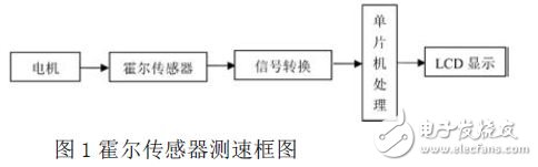
The measurement of the rotational speed actually measures the frequency of the periodic pulse signal caused by the rotation of the rotor. The Hall element velocimetry method uses a Hall switching element to measure the rotational speed.
The Hall switching element includes a voltage stabilizing circuit, a Hall potential generator, an amplifier, a Schmitt trigger, and an output circuit. The output level is compatible with the TTL level. A disc is mounted on the motor shaft. The disc is equipped with a number of small magnetic steels. The more small magnetic steel, the higher the resolution, the Hall switch is fixed near the small magnetic steel, when the motor rotates. Whenever a small magnetic steel turns over the Hall switch, the Hall switch outputs a pulse and calculates the number of pulses per unit time to determine the rotational speed of the rotating body. Its system block diagram is shown in Figure 1.
2 system hardware circuit design
The system includes a Hall sensor, an isolation shaping circuit, a main CPU, a display circuit, an alarm circuit, and a power supply. The measurement process is a coaxial connection between the Hall sensor and the motor shaft for measuring the rotational speed. Each revolution of the crankshaft generates a certain number of pulses, which is output by the Hall device circuit, and is sent to the MCU for processing after isolation and shaping. After receiving the signal, the value data is processed and displayed on the LCD liquid crystal display.
Once overspeeded, the CPU responds with a buzzer.
2.1 Sensor selection
The first step in measuring the motor speed is to express the motor's speed as a pulse signal that can be recognized by the microcontroller to perform pulse counting. The use of Hall devices for detecting pulse signals has the advantages of firm structure, small size, light weight, long life, and convenient installation. When the motor rotates, the sensor is driven to generate a pulse signal corresponding to the frequency, and after signal processing, it is output to a counter or other pulse counting device to measure the rotational speed.
2.2 Microprocessor selection
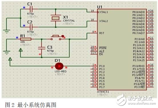
To reduce size and power consumption, the more commonly used and economical AT89S52 microcontroller is used: the AT89S52 is a low-power, high-performance CMOS 8-bit microcontroller with 8K in-system programmable memory. The minimum system includes the AT89S52 interface circuit, crystal oscillator circuit and reset circuit of the single chip microcomputer. as shown in picture 2.
2.3 Counters and timers
The advantage of using an on-chip counter is to reduce the cost of the microcontroller system. Each pulse will generate a count of T1. After the 100ms interrupt generated by T0 is completed, the number of interrupt overflows of T1 is the number of pulses required. The system count section uses an on-chip counter. The timer portion can be generated by an on-chip always signal.
2.4 Signal Processing Circuit
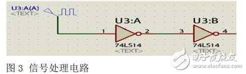
The Hall sensor is used to measure the rotation speed, and the detected signals are pulsed one by one, so there is no need to perform analog-to-digital conversion. After the signal passes through the sensor, the clutter can be filtered and directly connected to the single-chip microcomputer for counting processing. Because it is a digital pulse signal, the two reverse operations are used for filtering to achieve the purpose of isolation and shaping. The hardware splicing is shown in Figure 3. The 74LS14 is a six-bit inverter.
2.5 System Design Block Diagram
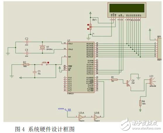
In the actual measurement, the Hall sensor is fixed on the bottom plate of the DC speed measuring motor, and a magnet block is fixed on the shaft of the motor opposite to the Hall probe. Each time the motor rotates, the Hall sensor sends a pulse signal, such as Figure 4 shows.
3 detection system software design
There are 4 basic steps that need to be taken to measure the motor speed: 1 is the control mode; 2 is the determination of the counting mode; 3 is the signal input mode; 4 is the reading of the counting value. The measuring process is that the Hall sensor for measuring the rotational speed is coaxially connected with the motor shaft. Each revolution of the crankshaft generates a certain number of pulses, which are output by the Hall device circuit. After the isolation shaping circuit, it becomes the counting pulse of the revolution counter. By controlling the counting time, the counter value of the counter can be realized. The main CPU processes the value data and displays it on the LCD.
Radiators in this case are manufactured with Stainless steel (SS304, SS316 and SS316L).
These radiators are manufactured with both 1mm CRCA sheet and 1.2 mm CRCA sheet as required and centre distance varying from 600 mm to 4000 mm. Stainless steel radiators can be offered with and without paint.
Through the method, the stainless steel plate type radiator for the transformer is simple in structure, free of complex treatment process on the surface of the radiator, not prone to oxidizing and corroding, long in service life, and high in welding strength.
Stainless Steel Radiator,Stainless Steel Transformer Radiator,Stainless Steel Cooling Radiator,Stainless Steel Weather Proof Radiator
Shenyang Tiantong Electricity Co., Ltd. , https://www.ttradiator.com