PLC programming typically involves several key steps that ensure the system operates efficiently and meets all functional requirements. Understanding these steps is essential for both beginners and experienced engineers working with industrial automation systems.
1. Preparation before programming
Before starting any programming, it's crucial to thoroughly understand the system's overall function, scale, control mode, and the types and quantities of input/output signals. You should also consider how the PLC will interface with other devices, its communication capabilities, and the specific control functions required. This preparation helps in forming a clear vision of the entire control system. Once you have this overview, you can further analyze the controlled object, classify the control functions based on response requirements, signal usage, or control area, and determine the physical locations of sensors and actuators. Understanding the nature and scale of each signal is vital for designing an effective program.
2. Design block diagram
Based on the software design specification and the actual conditions of the control system, define the basic structure of the application program. Create a block diagram that represents the program’s architecture according to standard design practices. Then, develop flowcharts for each functional unit based on the process requirements. These diagrams help visualize the logic and flow of the program, making it easier to implement and debug later.
3. Write the program
With the block diagram in place, start writing the program step by step. As you write, make sure to add comments and documentation to clarify the purpose of each section. This not only makes the code more readable but also simplifies future maintenance and modifications.
4. Program debugging
Debugging is a critical phase where each functional unit is tested individually. Input signals are simulated, and output responses are monitored to ensure everything works as expected. After individual units are verified, the entire program is tested, and interfaces between different modules are checked. Debugging can be done in a lab environment or on-site. If testing occurs on-site, the PLC system must be isolated from live signals, and the power supply to I/O modules should be disconnected to prevent unintended equipment operation. The goal during debugging is to identify and fix errors efficiently, following the principle of “focus on finding errors and focus on correcting them.â€
5. Write the program manual
Finally, document the entire process by creating a comprehensive user manual. This includes explaining the control requirements, program structure, flowcharts, and installation instructions. A well-documented program ensures smooth operation and makes it easier for others to understand and maintain the system in the future.
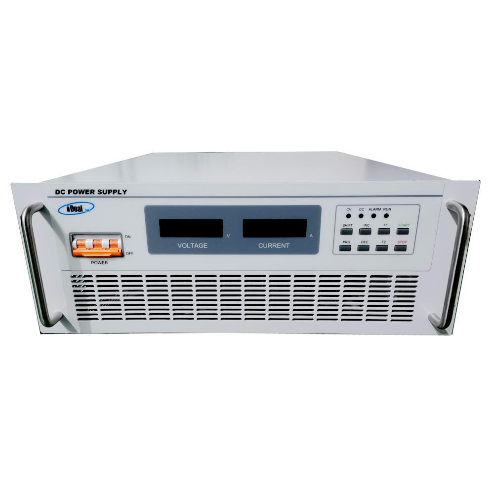
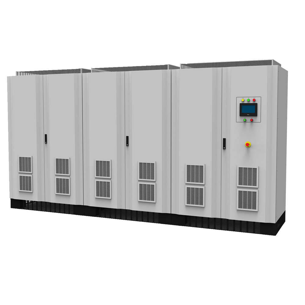
The MTP series DC Power Supplies are High Power DC power supplies developed by iDealTek-Electronics based on IGBT semiconductor components, adopting AC/DC power processing topology with full-bridge phase-shift soft-switching technology. This series of High-power DC power supplies have the most output models and the widest output range in the company's DC power supply series, from 3KW ~ 30KW integrated in 19-inch standard rack-mounted high-precision DC power supplies to 45KW ~ 2000KW with casters or floor-standing Cabinet type High Power DC power supplies, output voltage up to 2000VDC, output current up to 6000A.


This series of High-power AC - DC power supplies are equipped with a reliable two-stage conversion mechanism drive logic circuit and a fast control loop optimized by iDealTek-Electronics. Which balances the requirements of low output ripple and fast DC output response speed, making this series of High-power switching power supplies can provide high-precision, low ripple, high-stability and High-power DC output with fast response speed feature of the switching power supply. All MTP series DC power supplies are equipped with a short-term 2 times rated current overload capacity (Except for some high-current output models) to cope with the inductive and mixed load's demand for high-current output at the moment of starting.
The full range of MTP series high-power DC power supply adopts digital control circuit. You can set and control the power output through the buttons on the front panel of the power supply (3KW ~ 30KW) or LCD touch screen (45KW ~ 2000KW). The high-precision 4 1/2-digit LED (3KW ~ 30KW) or LCD (45KW ~ 2000KW) provides intuitive, high-precision output display and measurement functions. At the same time, the full range of MTP high-power DC power supplies are equipped with RS485 interfaces as standard, following the MODBUS-RTU international communication protocol, which can realize remote control and operating status monitoring of the power supplies.
At present, this series of High Power DC power supplies are mainly used in Battery charging testing, DC motor testing, Photovoltaic inverter testing, and various cutting-edge applications that require High-power DC output.
High-power DC Power Supplies, High Power AC - DC Supplies, High-power Switching Power Supplies, High-power AC DC Supplies, High-power Power Supplies
Yangzhou IdealTek Electronics Co., Ltd. , https://www.idealtekpower.com