Light-emitting diodes (LEDs) are gaining wider and wider applications due to their long life and high reliability. LEDs have been used in cars, street lights, outdoor signs and so on. In addition, with the development of new colors and new critical applications, the need for cost-effective testing methods to ensure LED reliability continues to grow. With the advent of high brightness and organic LED technology, the measurement performance and capacity requirements of test equipment are also increasing.
LED luminescence is the result of the transition of charged particles between semiconductor energy gaps. The size of the energy gap determines the wavelength of the luminescence. The development of LEDs has produced surface and edge illuminating techniques that change performance specifications such as wavelength and power characteristics.
This article describes methods and issues for building a production test system solution for testing single and multiple (array) LED devices.
Test introduction
High performance LEDs typically require five tests. These include three tests on the DC spectrum (forward voltage, reverse breakdown and leakage current tests) and two tests on the spectrum (light intensity and wavelength check). In a production environment, usually only DC testing involves testing capacity issues. Optical tests, while useful, are usually slow and generally reserved for engineering or quality control experiments. The various test and test requirements are detailed below.
DC test
Figure 1 shows the test points for the three DC tests presented in this article.

   Figure 1: Typical LED DC IV curve and test points
Forward voltage test (VF)
The VF test verifies the forward operating voltage of the visible LED. Beyond this operating voltage, a large increase in circuit current will result in a significant increase in the forward voltage, as shown in Figure 1. A specific forward bias current (eg, 10 mA) is applied to the LED over a specified period of time (eg, 1 ms) to measure the voltage drop across the LED. The result of the measurement is typically on the order of a few hundred millivolts.
Reverse breakdown voltage test (VR)
The VR test verifies the reverse breakdown voltage of the LED, similar to a diode. When the voltage is higher than this voltage, a large increase in the reverse bias current causes the reverse voltage to vary little. The technical indicator for this parameter is usually a minimum. The test provides a lower reverse bias current for a specified period of time while measuring the voltage drop across the LED. The measurement results are usually on the order of a few volts to tens of volts.
Leakage current test (IL)
The IL test verifies the leakage current of the LED, that is, the small current leaking in the LED when the reverse voltage is lower than the breakdown voltage. The test is loaded with a specific reverse voltage, and after a certain period of time, the corresponding current flowing through the LED is measured. The test process verifies that the measured leakage current is below a certain threshold. The measurement of these currents is usually on the order of nanoamps to milliamperes.
Optical test
Light intensity and radiation intensity test
The intensity of the illuminating (i.e., illumination) intensity is usually expressed in lumens/sphericity or candela. Its size range usually ranges from millicandela to several candelas. We can use this parameter to calculate the radiant intensity, expressed in watts/sphericity. The radiation intensity measures the total output (power) of the LED, while the luminous intensity measures the output (power) in the visible range. Radiation intensity ranges from slightly less than 1 μW/sr to tens of mW/sr. The luminous efficiency can be calculated by dividing the total luminous output (lumens/watt) by the input power. Light intensity is usually measured using a photodetector (PD). The magnitude of the reverse leakage current flowing through the PD is proportional to the intensity of the light that is incident on it. Therefore, if the LED is used to illuminate the PD while measuring the corresponding leakage current on the PD, the illumination intensity can be estimated. When measuring light intensity using this method, the entire test system capable of DC and optical testing can be constructed using only a high-speed DC tester. If you are not willing to use this DC test method, you must use a cumulative ball, which is not discussed in detail in this article.
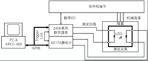
Figure 2: Block diagram of a typical test system for visible light LED production testing based on a digital source meter/electrometer
Note: The cumulative ball is required in the test fixture for illuminating and radiant intensity measurements.
Wavelength and color test
We usually use a spectrometer to measure the wavelength, which measures the main and peak wavelengths of the LED output. The output spectrum of an LED is called a farfiel pattern (FFP), similar to a normal curve centered on the peak wavelength of the LED. The full width at half maximum (FWHM) is calculated as the spectral bandwidth at half-intensity and is used to represent the operating wavelength range of the LED. Color information from the LED output can be measured using the ISO/CIE standard colorimetric system, which measures output colors based on three primary colors (red, blue, and green).
Test system introduction
Single LED test system
The LED is placed in the test fixture and connected to the input of the source meter. The placement of the device and the connection of the device under test (DUT) is usually done by the component robot to automate the production process. Test fixtures are usually protected from light to prevent test data errors due to ambient light. A photodetector (PD) is integrated into the test fixture and is tested when the robot places the LED into the test fixture. Figure 2 shows the structure of the typical DC characteristic analysis system described above.
The SourceMeter can perform three DC tests on the LED. Since this instrument can provide a current source or voltage source of any polarity, all DC characteristic analysis tests can be performed without flipping or moving the LED placed in the initial test position. The digital source meter is used in conjunction with an electrometer to measure the amount of light intensity. To analyze the illumination intensity of the LED, the digital source meter needs to scan the multi-point current within the working (voltage) range of the LED (as shown in Figure 3a), and use a 6517A to measure the illuminance through the PD (eg Figure 3b). For high-volume applications, light intensity is typically measured at only one or a few test points.

Figure 3a: LED measurement circuit
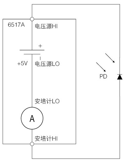
Figure 3b: Photodetector power supply circuit
Multi/array LED system
For LED arrays, multi-die packages or burn-in test applications, we often need to test many LEDs simultaneously. The most cost-effective way to test multiple devices at once is to integrate the switches in the test system. Aging tests typically require a delayed power on the LED, which requires a dedicated power supply function without a switch. The measurement of PD in the aging test system generally uses multiplexed methods to monitor LED performance at different times. Figure 4 shows an example of a LED switch test system configuration. The actual system can be configured with any number of diodes to support various electrical specifications.