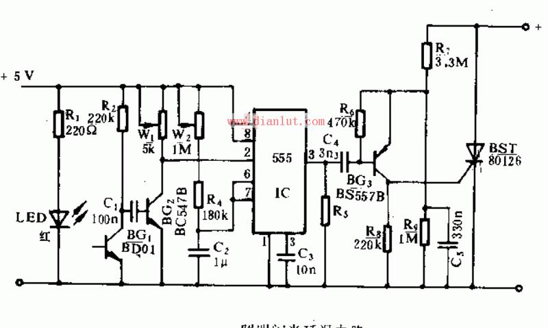
 In the circuit diagram, the light-emitting diode D1 and the phototransistor BG1 form a light gate. When the light is blocked, a positive pulse voltage will be generated at R2, which is amplified by BG2 and applied to the input terminal of the 555 time base circuit. After a delay, the time base circuit outputs a negative pulse signal to make BG3 and the thyristor Pass, the trigger glows. In the circuit diagram, the light-emitting diode D1 and the phototransistor BG1 form a light gate. When the light is blocked, a positive pulse voltage will be generated at R2, which is amplified by BG2 and applied to the input terminal of the 555 time base circuit. After a delay, the time base circuit outputs a negative pulse signal to make BG3 and the thyristor Pass, the trigger glows. |
Waterproof Speaker,Full Range Loud Speaker,Entrance System Speaker,Waterproof Multimedia Speaker
Jiangsu Huawha Electronices Co.,Ltd , https://www.hnbuzzer.com