The standing wave ratio (VSWR) is used to detect the operating status of the antenna feeder system, the RF connector, and all RF devices connected to the base station. Too high VSWR will result in dropped calls, high bit error rate, and the resulting attenuation of transmit/receive power will result in a narrow cell coverage radius.
Only when the load impedance is exactly matched to the source impedance can the signal be transmitted from the source to the load. For the base station system, the signal source is the transmitter, the load is the antenna feeder subsystem, and the antenna feeder subsystem includes an antenna, a feeder, a radio frequency connector, and an auxiliary device such as a lightning arrester. If the load and the signal source are not perfectly matched, some of the signal will be reflected back to the source. This is undesirable. At this time, forward and reverse waves are generated. These two signals are combined to form. Standing wave. The standing wave ratio (VSWR) is the ratio of the maximum level to the minimum level of the standing wave, and its size ranges from 1:1 (complete match) to ∞.
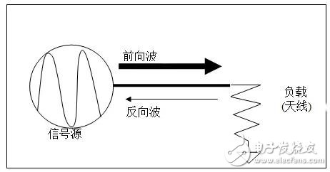
The generation of reverse waves due to incomplete impedance matching

Partial reflection when the image wave is to the media interface
We can calculate the VSWR by the reflection coefficient Γ or the return loss RL. Here we list the calculation formulas of the reflection coefficient Γ , the return loss RL and the VSWR:

among them,

Acceptable VSWR range
Since we are unable to achieve 100% load and source impedance matching, there will always be some signals that are inevitably reflected back by the antenna, so we need to determine a VSWR range as a measure of acceptable VSWR. Usually we use 1.13:1 – 1.38:1 as the VSWR metric. In addition, return loss can also be used as a measure. The ratio of forward power to reverse power is the return loss. If 40dBm forward power and 20dBm reverse power are known, then we can calculate the return loss. It is 20dB. If the output power of the base station is known to be 20W and the return loss is 16dB, then we can calculate the reflected power as 0.5W. Usually we use 16 –24dB as a measure of return loss.
Serious faults occur on the transmitter-to-antenna transmit path, resulting in very low return loss, such as loose RF connectors, antenna failure, feeder damage, lightning arrester breakdown, and filter/coupler damage. This severe VSWR failure will result in failures such as dropped calls, increased bit error rates, and reduced cell coverage radius.
Standing wave ratio from the perspective of power
From the power point of view, the standing wave ratio can be expressed as:
SWR = (√Po + √Pr)/(√Po - √Pr)
Po: power into the antenna system
Pr: power reflected from the antenna system
The relationship between the operation SWR and Pr/Po (reflection power percentage) is as follows:
Pr/Po = [(SWR-1)/(SWR+1)]^2
In fact, the standing wave ratio tester is basically a power meter, which can measure input power and reflected power.
What is standing wave?
A wave in which two columns of coherent waves of the same amplitude propagate in opposite directions on the same straight line are called standing waves.
Features: The valleys and peaks remain stationary, the waveform does not propagate forward, only vibrates in equilibrium position; the waveform does not move in space.
Generally, the electromagnetic wave on the transmission line is composed of a traveling wave (a wave transmitted forward) and a reflected wave. The standing wave ratio is a state in which the wave stays. For example, the larger the standing wave ratio, the more the wave stays in place, if the standing wave ratio is infinite. That means the wave is staying in place. Conversely, the reciprocal of the standing wave ratio can be defined as the traveling wave coefficient, which indicates the state of the wave travel, and the larger the traveling wave coefficient, the more the representative wave travels forward.

Standing wave and traveling wave
What is a match?
In mobile communication systems, accessories such as transmitters, antennas, feeders, RF connectors, and lightning arresters need to be connected by cables and connectors. Only when they are properly connected can the equipment operate normally. Under normal circumstances, people tend to pay more attention to the direction of the antenna, elevation angle, polarization, frequency selection and other steps. In the installation and debugging steps, the connection between devices is often neglected. These device components should be connected from the beginning to the end. Match this principle.
"Match", from the power point of view, means the maximum output power, that is, the conjugate value (equal resistance, equal magnitude, opposite sign) of the load impedance in the power supply circuit is called "matching". The purpose of matching is to get the maximum output power. From the perspective of the transmission line, it means lossless transmission, that is, when applied to a transmission line, the load impedance is made equal to the characteristic impedance of the transmission line, which is called "matching". The purpose of matching is to eliminate the reflection caused by the load, avoid standing waves, and make the load get the maximum power.
In mobile communication systems, many places need to be matched. The receiving antenna must have the same polarization as the transmitting antenna and have the same direction of rotation to achieve polarization matching to receive the full energy. All parts of the feeder connection and the connections between the components need to be matched. In the mobile communication system, as long as there is a mismatch, the signal is reflected in the middle of the component and between the feeders, thereby degrading the signal quality and increasing the noise. Therefore, for the installation and debugging users, it is necessary to do every step to ensure that the system is matched.
Antenna-stationary wave ratioThe meaning of the antenna standing wave ratio indicates an indicator of the degree of matching between the antenna feeder and the base station (transceiver).
The definition of the standing wave ratio in the antenna:
VSWR=Umax/Umin
Umax--the antinode voltage on the feeder;
Umin--the valley voltage on the feeder.
The standing wave ratio is generated by the fact that the incident wave energy is transmitted to the antenna input terminal B without being completely absorbed (radiated), and the reflected wave is generated and superimposed.
The larger the VSWR, the larger the reflection and the worse the match.
Then, what are the disadvantages of the poor standing wave ratio? What is the acceptable standing wave ratio in engineering? An appropriate standing wave ratio indicator is to make a trade-off between the amount of energy lost and the cost of manufacturing.
(1) VSWR "1", indicating that part of the power input to the antenna is reflected back, thereby reducing the radiated power of the antenna;
(2) Increased feeder loss. 7/8" cable loss 4dB/100m, measured at VSWR = 1 (full match); with reflected power, the energy loss is increased, thereby reducing the input power of the feeder to the antenna;
(3) At feeder input A, when the mismatch is severe, the output power of transmitter T does not reach the design rating. However, modern transmitter output power allows for rated power to be reached in certain mismatch conditions (VSWR "1.7 or 2.0").
The relationship between the standing wave ratio and the reflected power is as follows.
It can be seen that it is not necessary to pursue a standing wave ratio of 1.1 or less. Generally, 1.5 is enough, and 96% are all launched.
Standing wave ratio reflectivity
1.0 0.00%
1.1 0.23%
1.2 0.83%
1.3 1.70%
1.5 4.00%
1.7 6.72%
1.8 8.16%
2.0 11.11%
2.5 18.37%
3.0 25.00%
4.0 36.00%
5.0 44.44%
7.0 56.25%
10 66.94%
15 76.56%
20 81.86%
SEMI-ELECTRIC STACKER POWER UNIT
Hydraulic Power Unit For Car,Hydraulic Lifter Remover,Electric Hydraulic Valve For Tractor,Car Lift Hydraulic Power Unit
CHANGZHOU ROHN HYDRAULIC SCI-TECH CO.,LTD , https://www.rohnhydraulic.com