By connecting the LCD 1602, buzzer and single path tracking sensor module to the GPIO pin of the Raspberry Pi, the distance or color of the object is detected by a single path tracking sensor. When the object distance is too close, the path sensor module output is low at this time. At this time, the LCD1602 displays "DETECTED: YES", and the buzzer sounds. When the object is black or the distance is long, the buzzer has no output, and the LCD 1602 displays "DETECTED: NO".
DIY tools:
It mainly includes Raspberry Pi B+, LCD1602, buzzer, single path tracking sensor module. Its main role is as follows:
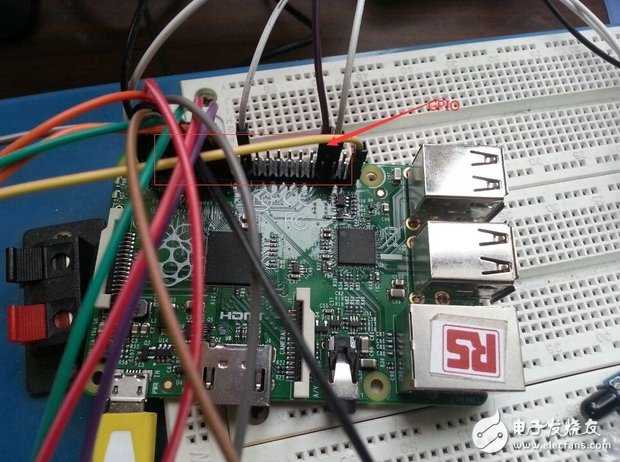
Raspberry Pi: The main control chip controls output according to external input. Mainly use the GPIO port of the Raspberry Pi
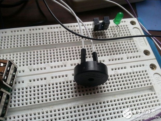
Buzzer: A passive buzzer that is driven by a PWM wave and driven by a Raspberry Pi.
LCD1602: Display the necessary information to output the device.
Single path tracking sensor module: Input device. The distance of the object can be judged by the reception of the reflected infrared rays. When the detected object is within the detection range, the infrared rays are reflected back and the intensity is large enough, and the output of the module is low, indicating that the diode is illuminated. Otherwise output high level.
Assign Raspberry Pi pins
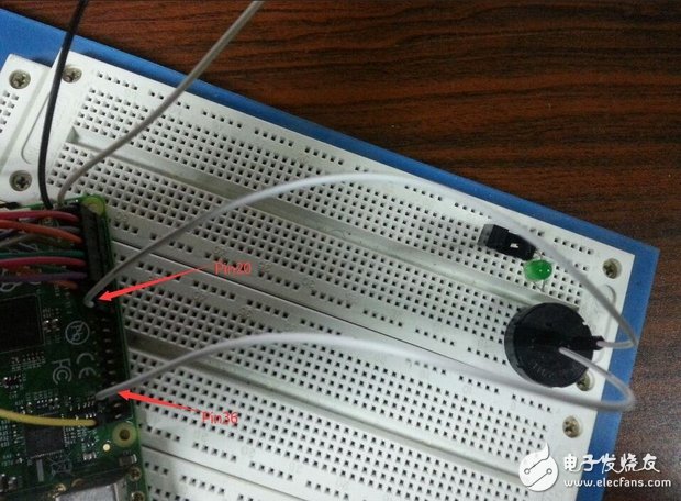
Because the B+ board is used, so there are more GPIO ports. I will connect other small modules directly to the GPIO port of the Raspberry Pi. Don't worry that the GPPIO port is not enough. The Raspberry Pi is connected to the buzzer and uses two pins, Pin20 and Pin36. Pin20 is the Ground pin of the Raspberry Pi, so I use the Pin36 pin (GPIO16) to send a PWM wave to drive the buzzer.
Next is the Raspberry Pi and LCD1602 connection. In particular, the main RW pin of the LCD1602 must be grounded, otherwise the Raspberry Pi may be burned out.
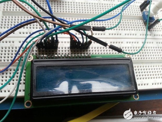
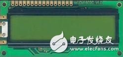
For LCD1602, everyone should be familiar with it, if you have played the microcontroller before. This is how it looks, we can use it to display letters, numbers, symbols and other information. It has a total of 16 pins on the back and can display 16X02 characters at the same time. For some small apps and demos, it's still a great tool.
What I did today is to connect the Raspberry Pi to the LCD1602. Then the first question comes out? How do we connect? This requires us to know the output information of the GPIO port of the Raspberry Pi. We also need to know the pin information of the LCD1602. Only when this is the same number, can the LCD be powered up correctly, and we can formally use the LCD1602.
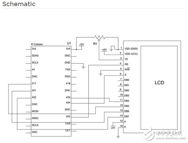
This is the schematic of the connection between the GPIO and LCD1602 I use for the Raspberry Pi.
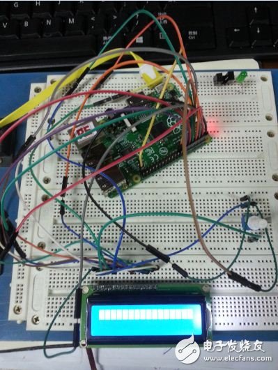
Below is my actual wiring diagram.
Here are a few points to talk to:
(1) The Raspberry Pi of the schematic is the B version. I actually use the B+ board, but the pin number has not changed. Everyone must also pay attention to the difference between the actual and the schematic
(2) Since the Raspberry Pi has few pins, we do not use the 7~10 pins of the LCD.
(3) Since the Raspberry Pi has no overcurrent protection and is very fragile, the RW pin of the LCD1602 is grounded during use. Otherwise, attempting to read data from the LCD1602 may burn the Raspberry Pi.
(4) In the schematic diagram, Ri is a potentiometer, that is, a 10KΩ sliding rheostat, which can adjust the brightness of the LCD.
Finally, when we check, we must not have a short circuit to ensure grounding. We can power it up. At this time, the LCD should be lit. We rotated the potentiometer and saw that the small grid on the LCD disappeared or appeared.
The Raspberry Pi is connected to the single-path tracking module. There are three pins, one of which is connected to the positive voltage, Pin1 and the Raspberry Pi output is 5V. A grounded, Pin34, Ground of the Raspberry Pi. The other is the signal output, Pin3. In the program, the distance of the object is judged by judging the voltage of the Raspberry Pi pin.
After completing these steps, we will basically complete the hardware connection. The next step is the implementation of the software.
Software Implementation
This part mainly introduces the software part of my small application.
Software is the core to achieve this function, mainly including the following parts:
(1) sensing module, sensing the input of the wireless sensing module
(2) Drive the buzzer, need to generate PWM wave
(3) Display module, LCD1602 displays different information according to different sensing conditions.
We can learn from the online information in these three parts, but we must make some modifications according to our own situation. Of course, I highly recommend the following website: http://wiringpi.com/. The functions used in my program are in the following directory. Everyone clicks in and finds the prototype after looking at the program behind me!
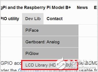
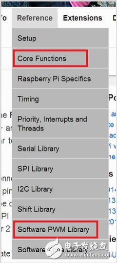
Wiring is a control function specially written to better apply the Raspberry Pi's GPIO port. This control function contains a lot of library functions that have been written, and we just need to call them according to the rules. Of course, when using these functions, we need to change some parameters according to the connection status of our Raspberry Pi GPIO port.
kolon aramid yarn,strong fiber,high-performance,durable,lightweight
Huizhou Fibercan Industrial Co.Ltd , https://www.fibercannetworks.com